
























Service Hotline
News

News
Effect of high temperature environment on transistor performance
2022-03-17
638
Specifically, it is a very simple serial port RS485 circuit. The specific circuit is as shown in the figure below. After using this circuit, there is no need to use separate signals to manage the sending and receiving time sharing of the 485 chip (isn't it very convenient, I think so too).
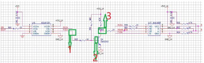
The problem is that this circuit appeared. When we did the environmental experiment at 55 degrees, there was no problem at all. We should send and receive, but when we got to the user's place, it hung up after working for a while, and nothing happened. After my on-site inspection (stepping), do you know where the user is? It was placed next to an engine that generates a lot of heat (fuck me, forget it, the customer is God). I personally measured the ambient temperature and it was above 48 degrees. In order to prevent dust, my board and a main control that generates a lot of heat were placed in a box, and there was no fan. This caused the temperature inside the box to reach over 70 degrees (are you going to have a barbecue?). There is no way to say which installation environment is not convenient for measurement. I was also desperate, and then I had an idea and said to the embedded software guy behind me, is there something wrong with your software configuration? ARM will reduce frequency when it gets too hot. Did you not configure it properly, causing problems with sending and receiving (because I don’t know the problem at the moment). Then the guy said aggrievedly, "It’s nothing special. I almost tore through the manual and didn’t see it." I first expressed my deep sympathy to him and then said, "Brother, I’ll go back and help you think about what went wrong."
After returning to the company, I blew hard on the ARM with a heat gun, but nothing happened. Good guy, the pot couldn't be shaken off. I blew the rest of the circuit step by step. When I blew it to the triode (Q4 in the picture), no data was obtained. It seemed to be the triode's problem, but misfortunes never come singly. After I didn't blow it, there was no data when the temperature dropped. Could it be that it was blown? If you look carefully, you can see that the resistor has been blown off (F***, there is no such thing as smooth sailing on the road of hardware). After soldering the resistor, turn down the air volume, increase the heat and continue to blow. If something is wrong, then lock the target and measure the waveform.
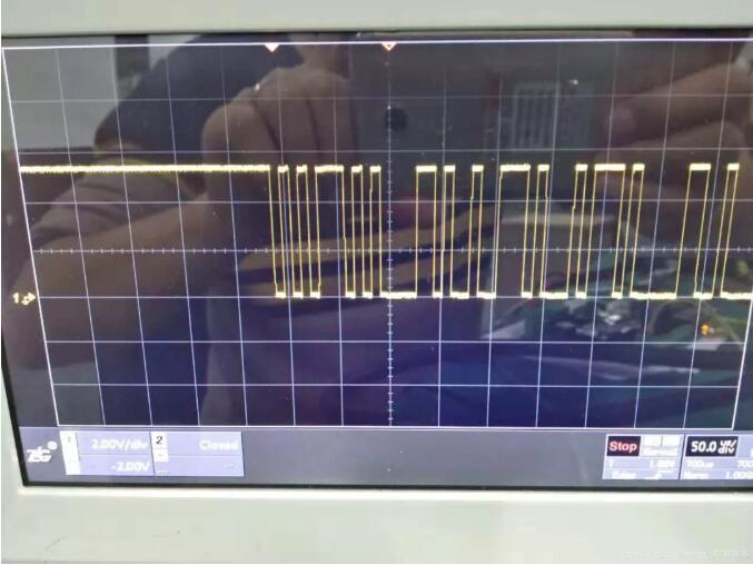
Measure points 1, 2, and 3 marked in the above figure respectively. The current limiting resistor used in the circuit design is 1K and the triode is 9013. First, measure the waveforms of three test points at room temperature. The first waveform is the output pin of the isolation chip ADuM1201. The waveform is as shown in the figure below. The output voltage amplitude is 5V (ignore the figure in the background).
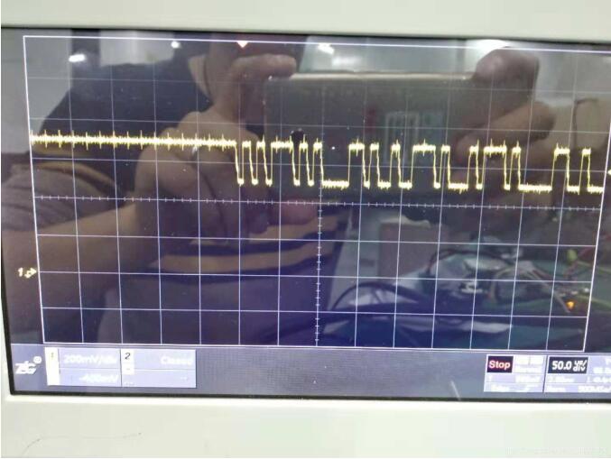
The second point waveform is the base control voltage of the 9013 triode. The waveform is as shown in the figure below. The peak value of the output voltage is about 700mV, and the fluctuation range is about 200mV. That is, when the level is 0.7V, the triode is turned on, and when the level is 0.5V, the triode is turned off.
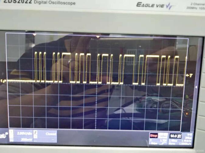
The third point waveform is the collector electrode voltage of the 9013 triode tube. The waveform is as shown in the figure below, and the output voltage amplitude is about 5V.
Then I went online with my hand, which is a hair drying expert. I was blowing on it for a while, and I had to measure the waveform with my other hand. Fortunately, no blisters were caused by the iron (otherwise, it would be considered a work injury). I re-measured the above three measurement points. The waveform of the first point is shown in the figure below. The waveform is basically the same as the waveform before heating, so heating will not change the output voltage characteristics of the ADuM1201 isolation chip.
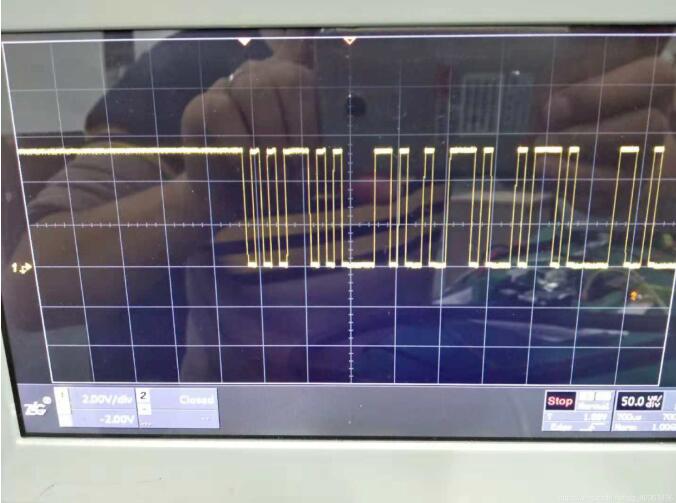
Then continue to measure the second point. When the temperature continues to be heated to about 55 degrees, the second point waveform is as shown in the figure below. The fluctuation range of the voltage becomes smaller than about 100mV, that is, the high level is reduced to 0.6V, but the low level is still about 0.5V. As the temperature continues to rise, when the temperature reaches 65 degrees, the second point voltage basically remains at 0.5V, and the transistor remains on, so RS485 cannot send data.
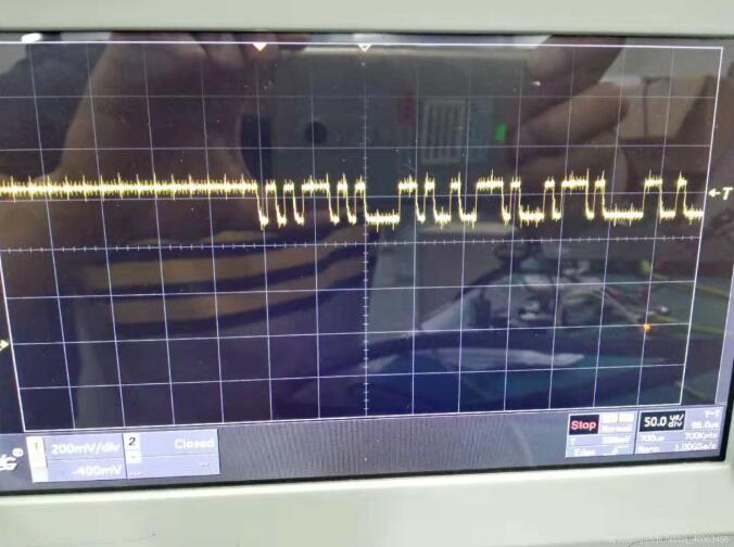
Okay, the third point is online. When the temperature is heated to about 55 degrees, the waveform of the third point is as shown in the figure below. As the temperature increases, the output voltage of the third point remains low, and the RS485 circuit is in the accepting state.
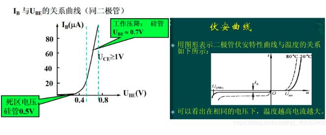
I K, isn’t this tricking me? Let me take a look at the characteristics of this triode (who asked me not to study hard when I was in school). The physical structure of the triode is two PN junctions. Its Ube voltage characteristics are as shown in the figure below. Its turn-on voltage is about 0.7V, and the base and emission voltage characteristics are the same as the diode characteristics. As can be seen from the figure on the lower right, as the temperature increases, Ube's characteristic curve shifts to the right as a whole, so the conduction voltage drop of the triode decreases, causing the RE pin that controls the MAX485 chip to always be at a low level, so data cannot be sent.
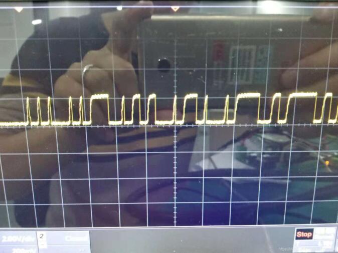
Now that I know the effect of temperature on the triode, let me change it. From the above analysis, we can know that the base of the triode is ultimately clamped to 0.5V because the 5V pull-up resistor of 10K and the current limiting resistor of 1K divide the base of the triode to 0.5V. After changing the current limiting resistor R65 to 0R, the waveform is as shown in the figure below. It can be seen that the voltage waveform fluctuates between 0V and 0.7V.
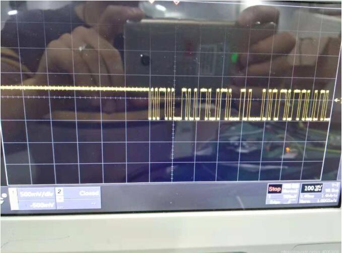
After changing to 0R current limiting resistor, continue to heat the RS485 circuit. The waveform is as shown in the figure below. It can be seen that there is no obvious change in the waveform, and the serial port can send data normally. However, because the base of the transistor forces the ADuM1201 transmit pin down to 0.7V, which increases the output current of the ADuM1201, it will have a serious impact on the life of the device during long-term operation. It is not my character to not change it thoroughly (mainly because I am afraid that it will cause trouble for me in the future).
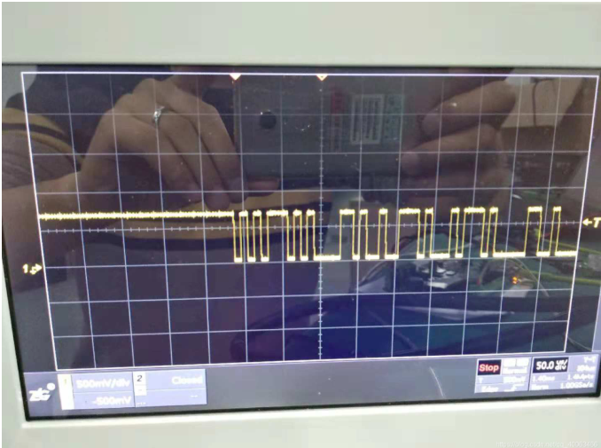
In order to completely solve this problem (once and for all), I thought hard (fake) and found out that the temperature characteristics of the triode led to a reduction in the base threshold voltage under high temperature operation. If only reducing the output current limiting resistance of the ADuM1201 would reduce the device life and affect product quality, I now changed the triode 9013 to the MOS tube GMS2302. Since the MOS tube is a voltage-controlled device, it does not consume too much power.
The gate voltage waveform of the MOS tube GMS2302 at room temperature is shown in the figure below. It can be seen that the waveform range is 0V to 5V.
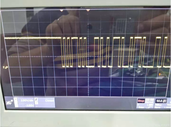
The gate voltage waveform when the temperature of the MOS tube GMS2302 is about 80 is as shown in the figure below. The voltage waveform does not change and the serial port can send data normally.
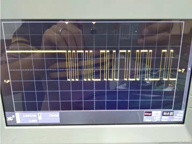
Therefore, in the design, I have to have the spirit of inquiring (hiding in pits) to completely solve the problem. This case is a case that I have personally experienced. Although it is not big, it is of great reference significance. The conclusion drawn is that it can guide us in the future hardware design process. If it is used as a switch, it is best to choose MOS tubes and reasonably choose current-limiting resistors.
Disclaimer: This article is reproduced from "Hardware Siege Lion". This article only represents the author's personal views and does not represent the views of Sacco Micro and the industry. It is only for reprinting and sharing and supports the protection of intellectual property rights. Please indicate the original source and author for reprinting. If there is any infringement, please contact us to delete it.
Company phone number: +86-0755-83044319
Fax/FAX: +86-0755-83975897
Email: 1615456225@qq.com
QQ: 3518641314 Manager Li
QQ: 332496225 Manager Qiu
Address: Room 809, Building C, Zhantao Technology Building, No. 1079 Minzhi Avenue, Longhua New District, Shenzhen
Related Recommendations
Exclusive Interview with Li Gang of Yunfan Ruida: The Precision of Millimeter-Wave Radar Products and the Warmth of Humanity
2026-07-22
2563
RF Passion, Craftsman’s Journey: Over 30 Years of Steadfast Dedication — Interview with Kinghelm Chief Engineer Mr. Qin hongxiang
2026-06-26
2725





 粤公网安备44030002007346号