
























Service Hotline
Solutions

Solutions
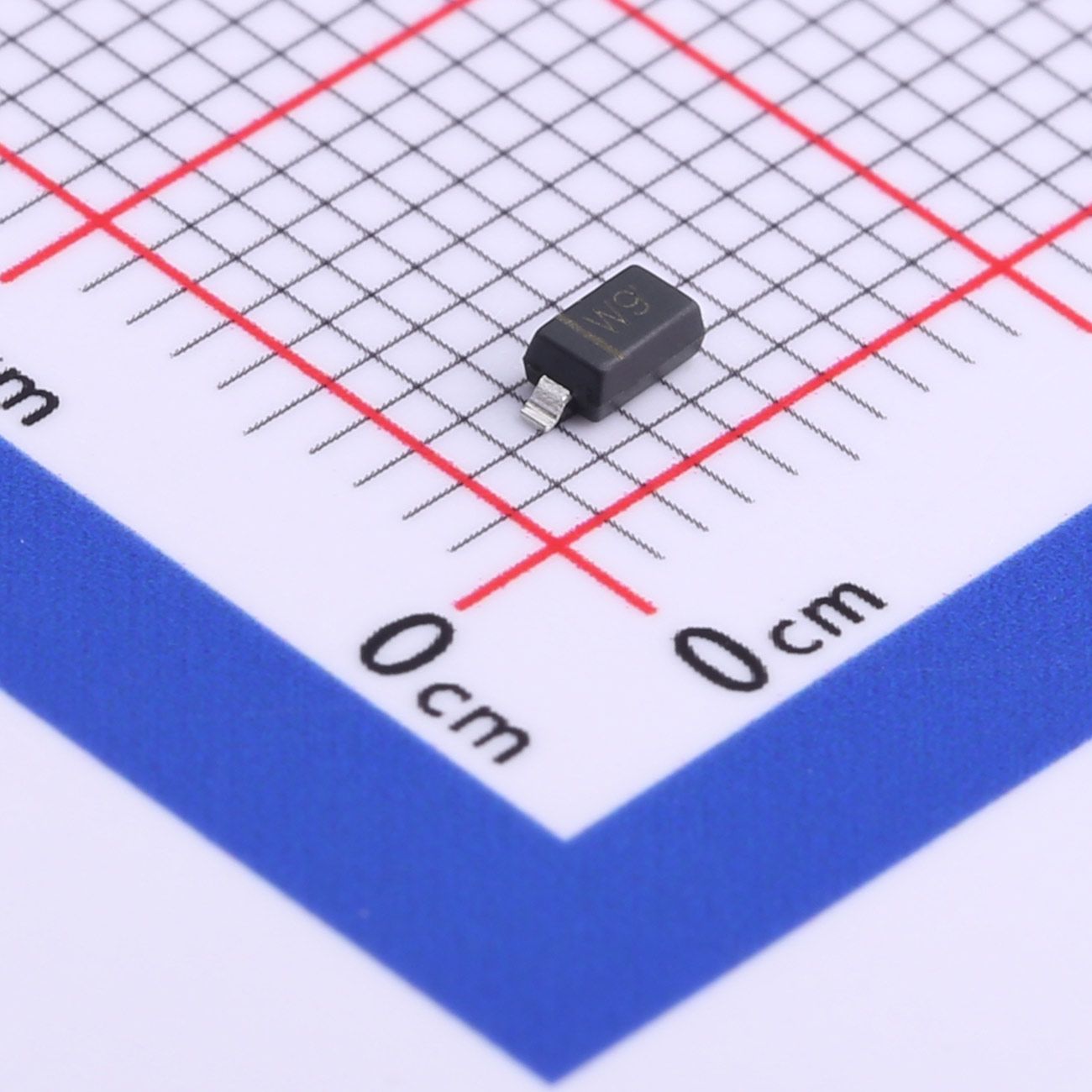
【Daily Highlight】The Voltage Regulator Diode BZT52C5V6
2026-09-30
750
Introduction:
In the realm of electronics, precision components play a pivotal role in ensuring stable and reliable circuit operation. Among these components, the BZT52C5V6 Zener diode emerges as a cornerstone of precision and versatility. This article aims to unravel the intricacies of the BZT52C5V6, spotlighting its specifications, features, and applications, elucidating its significance in contemporary electronic designs.
Slkor Voltage Regulator Diode BZT52C5V6 product photo
Specifications Overview:
The BZT52C5V6 Zener diode boasts a comprehensive array of specifications that underscore its prowess in diverse applications. Let's delve into its key parameters:
1. Nominal Zener Voltage (VZTyp): Central to the BZT52C5V6 is its nominal Zener voltage of 5.6V. This characteristic serves as a stable reference voltage, essential for precise voltage regulation and signal conditioning in various electronic circuits.
2. Power Dissipation (PD): With a power dissipation rating of 500mW, the BZT52C5V6 demonstrates its ability to handle moderate to high power levels while sustaining stable operation. This attribute is crucial for ensuring reliability under varying operating conditions.
3. Reverse Current (Ir): The BZT52C5V6 showcases a reverse current of 1μA at a reverse voltage of 2V. This low reverse current minimizes leakage, enhancing circuit efficiency and reliability, particularly in low-power applications.
Slkor Voltage Regulator Diode BZT52C5V6 specification
Applications:
The versatility of the BZT52C5V6 Zener diode makes it well-suited for a wide range of applications across diverse industries. Here are some notable applications:
1. Voltage Regulation: Leveraging its precise Zener voltage and robust power dissipation capability, the BZT52C5V6 excels in voltage regulation tasks. It finds application in power supplies, voltage reference circuits, and battery management systems, ensuring stable and reliable operation of electronic devices.
2. Signal Clipping and Limiting: In audio and communication circuits, the BZT52C5V6 plays a crucial role in signal clipping and limiting. By maintaining optimal signal levels, it preserves signal integrity and minimizes distortion in amplifiers, mixers, and communication equipment.
3. Overvoltage Protection: With its precise Zener voltage and low reverse current, the BZT52C5V6 provides effective overvoltage protection in sensitive electronic systems. By clamping excessive voltages, it safeguards against damage from voltage spikes and surges, ensuring the longevity of critical components.
4. Voltage Reference: The BZT52C5V6 serves as a reliable voltage reference in precision measurement and control systems. Its stable Zener voltage and low reverse current make it ideal for establishing reference voltages in instrumentation, data acquisition, and feedback control circuits.
Parameters of Slkor Voltage Regulator Diode BZT52C5V6
Conclusion:
In conclusion, the BZT52C5V6 Zener diode stands as a testament to precision, versatility, and reliability in electronic component design. Its precise Zener voltage, robust power dissipation capability, low reverse current, and stable performance make it an indispensable asset in a myriad of applications. Engineers and designers can confidently leverage the BZT52C5V6 to achieve precise voltage regulation, signal conditioning, overvoltage protection, and voltage reference tasks, driving innovation and progress in the ever-evolving field of electronics.
What is the advantages of Slkor products?Slkor's products are diverse and comprehensive, presented in a series. Slkor has accumulated strength and developed rapidly, with short R&D cycles and continuous iteration of products, constantly launching new products. Slkor has a clear development strategy, reasonable technical layout and cost control, and the company’s overall competitiveness is gradually improving. In the Internet era, Slkor has cracked the code of Internet development, and its ability to respond quickly and serve customers is another advantage.
About Slkor:
Slkor has research and development offices in Busan, South Korea, Beijing, China, and Suzhou, China. Most of the wafer manufacturing and packaging and testing are carried out within China. The company employs and collaborates with individuals and organizations worldwide, with a laboratory for product performance and reliability testing and a central warehouse located at its headquarters in Shenzhen. Slkor has filed for over a hundred invention patents, offers more than 2,000 product models, and serves over ten thousand customers globally. Its products are exported to countries and regions including Europe, the Americas, Southeast Asia, and the Middle East, making it one of the rapidly growing semiconductor companies in recent years. With well-established management systems and streamlined workflows, Slkor has rapidly enhanced the brand awareness and reputation of its "SLKOR" brand through its outstanding quality and standardized services. Its product range includes three major series: diodes, transistors, and power devices, with recent introductions of new products such as Hall elements and analog devices, expanding its presence in sensors, Risc-v microcontrollers, and other product categories.
BZT52C5V6To Product Page
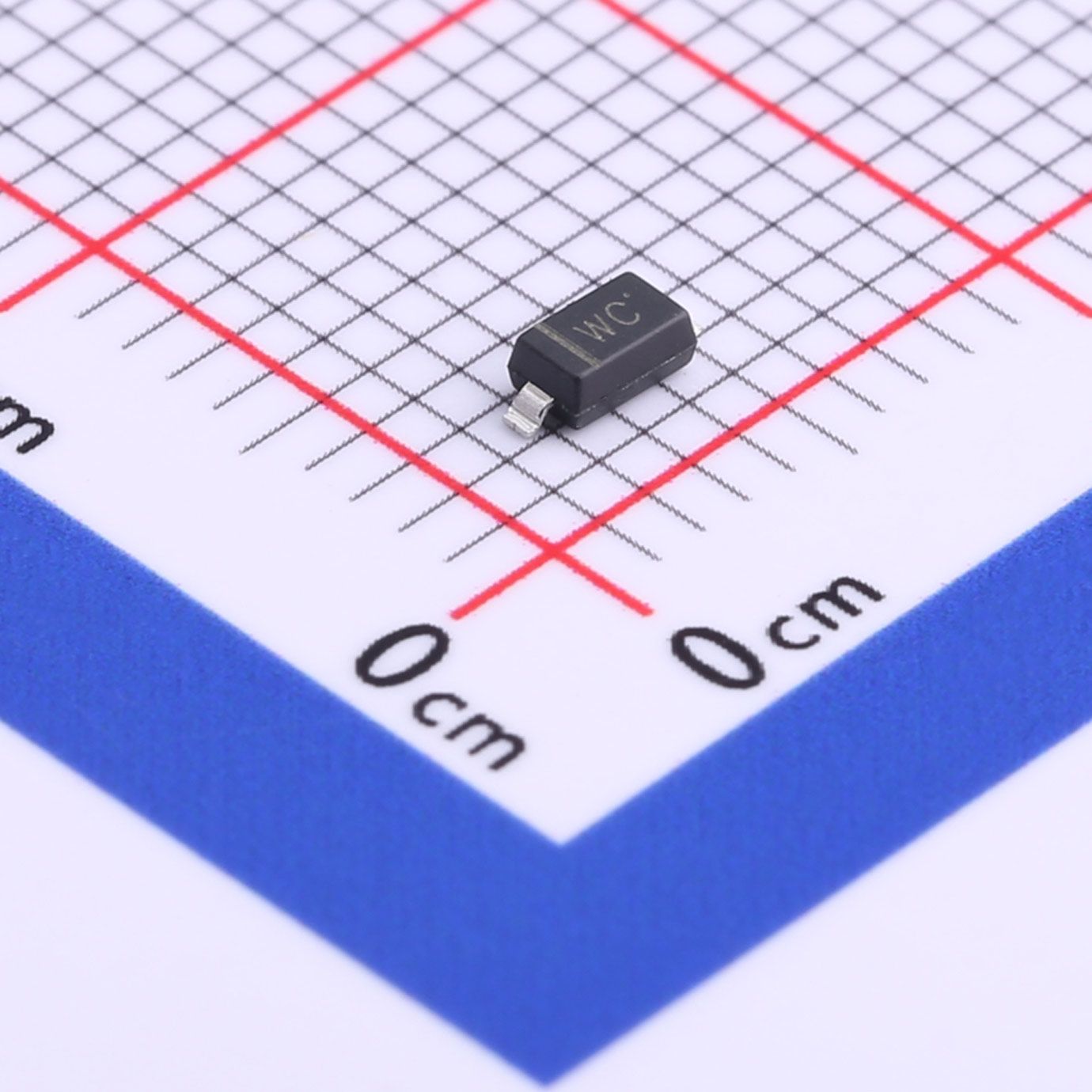
【Daily Highlight】The Voltage Regulator Diode BZT52C7V5
2026-09-30
754
Introduction:
In the intricate landscape of electronics, precision components serve as the bedrock of stability and reliability in circuitry. Among these components, the BZT52C7V5 Zener diode stands out for its precision and versatility. This article aims to delve into the intricacies of the BZT52C7V5, shedding light on its specifications, features, and applications, elucidating its importance in contemporary electronic designs.
Slkor Voltage Regulator Diode BZT52C7V5 product photo
Specifications Overview:
The BZT52C7V5 Zener diode presents a spectrum of specifications that underscore its capability in various applications. Let's delve into its key parameters:
1. Nominal Zener Voltage (VZTyp): At the heart of the BZT52C7V5 lies its nominal Zener voltage of 7.5V. This characteristic serves as a stable reference voltage, pivotal for precise voltage regulation and signal conditioning in electronic circuits.
2. Power Dissipation (PD): With a power dissipation rating of 500mW, the BZT52C7V5 demonstrates its ability to handle moderate to high power levels while maintaining stable operation. This attribute ensures reliability across a range of operating conditions.
3. Reverse Current (Ir): The BZT52C7V5 exhibits a reverse current of 1μA at a reverse voltage of 5V. This low reverse current minimizes leakage, enhancing circuit efficiency and reliability, especially in low-power applications.
Slkor Voltage Regulator Diode BZT52C7V5 specification
Applications:
The versatility of the BZT52C7V5 Zener diode renders it suitable for a plethora of applications across diverse industries. Here are some notable implementations:
1. Voltage Regulation: Leveraging its precise Zener voltage and robust power dissipation, the BZT52C7V5 excels in voltage regulation tasks. It finds utility in power supplies, voltage reference circuits, and battery management systems, ensuring consistent and reliable operation of electronic devices.
2. Signal Conditioning: In audio and communication circuits, the BZT52C7V5 plays a crucial role in signal conditioning, particularly for signal clipping and limiting. By maintaining optimal signal levels, it preserves signal integrity and minimizes distortion in amplifiers, mixers, and communication equipment.
3. Overvoltage Protection: With its precise Zener voltage and low reverse current, the BZT52C7V5 provides effective overvoltage protection in sensitive electronic systems. By clamping excessive voltages, it safeguards against damage from voltage spikes and surges, ensuring the longevity of critical components.
4. Voltage Reference: The BZT52C7V5 serves as a dependable voltage reference in precision measurement and control systems. Its stable Zener voltage and low reverse current make it ideal for establishing reference voltages in instrumentation, data acquisition, and feedback control circuits.
Parameters of Slkor Voltage Regulator Diode BZT52C7V5
Conclusion:
In summary, the BZT52C7V5 Zener diode epitomizes precision, versatility, and reliability in electronic component design. Its precise Zener voltage, robust power dissipation, low reverse current, and stable performance make it an indispensable asset across a myriad of applications. Engineers and designers can confidently leverage the BZT52C7V5 to achieve precise voltage regulation, signal conditioning, overvoltage protection, and voltage reference tasks, driving innovation and progress in the dynamic realm of electronics.
What is the advantages of Slkor products?Slkor's products are diverse and comprehensive, presented in a series. Slkor has accumulated strength and developed rapidly, with short R&D cycles and continuous iteration of products, constantly launching new products. Slkor has a clear development strategy, reasonable technical layout and cost control, and the company’s overall competitiveness is gradually improving. In the Internet era, Slkor has cracked the code of Internet development, and its ability to respond quickly and serve customers is another advantage.
About Slkor:
Slkor has research and development offices in Busan, South Korea, Beijing, China, and Suzhou, China. Most of the wafer manufacturing and packaging and testing are carried out within China. The company employs and collaborates with individuals and organizations worldwide, with a laboratory for product performance and reliability testing and a central warehouse located at its headquarters in Shenzhen. Slkor has filed for over a hundred invention patents, offers more than 2,000 product models, and serves over ten thousand customers globally. Its products are exported to countries and regions including Europe, the Americas, Southeast Asia, and the Middle East, making it one of the rapidly growing semiconductor companies in recent years. With well-established management systems and streamlined workflows, Slkor has rapidly enhanced the brand awareness and reputation of its "SLKOR" brand through its outstanding quality and standardized services. Its product range includes three major series: diodes, transistors, and power devices, with recent introductions of new products such as Hall elements and analog devices, expanding its presence in sensors, Risc-v microcontrollers, and other product categories.
BZT52C7V5To Product Page
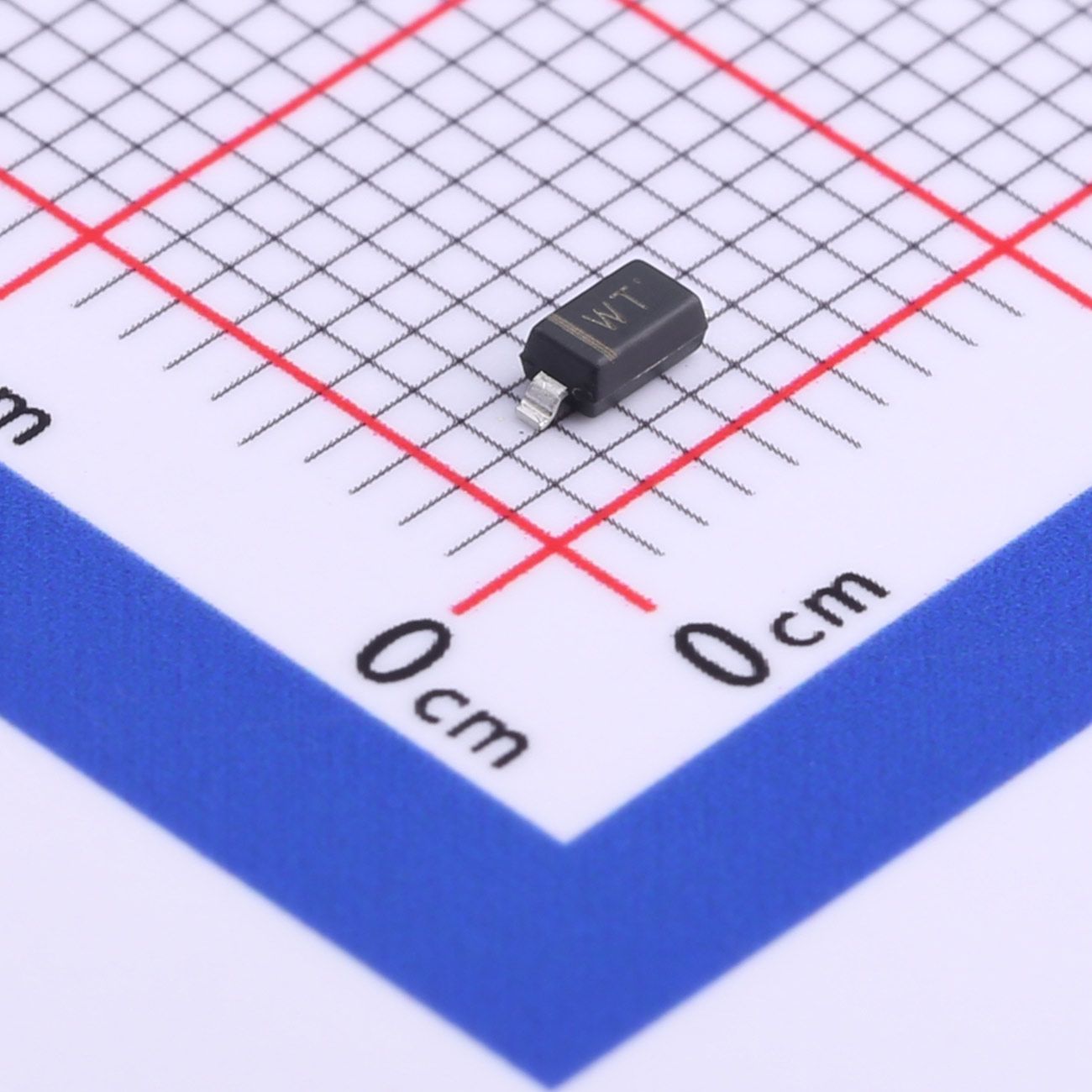
【Daily Highlight】The Voltage Regulator Diode BZT52C39
2026-09-30
738
Introduction:
In the realm of electronics, precision components play a pivotal role in ensuring stable and reliable circuit operation. Among these components, the BZT52C39 Zener diode emerges as a cornerstone of precision and versatility. This article aims to unravel the intricacies of the BZT52C39, spotlighting its specifications, features, and applications, elucidating its significance in contemporary electronic designs.
Slkor Voltage Regulator Diode BZT52C39 product photo
Specifications Overview:
The BZT52C39 Zener diode boasts a comprehensive array of specifications that underscore its prowess in diverse applications. Let's delve into its key parameters:
1. Nominal Zener Voltage (VZTyp): At the core of the BZT52C39 is its nominal Zener voltage of 39V. This characteristic serves as a stable reference voltage, essential for precise voltage regulation and signal conditioning in various electronic circuits.
2. Power Dissipation (PD): With a power dissipation rating of 500mW, the BZT52C39 demonstrates its ability to handle moderate to high power levels while sustaining stable operation. This attribute is crucial for ensuring reliability under varying operating conditions.
3. Reverse Current (Ir): The BZT52C39 showcases a reverse current of 100nA at a reverse voltage of 27.3V. This exceptionally low reverse current minimizes leakage, enhancing circuit efficiency and reliability, particularly in low-power applications.
Slkor Voltage Regulator Diode BZT52C39 specification
Applications:
The versatility of the BZT52C39 Zener diode makes it well-suited for a wide range of applications across diverse industries. Here are some notable applications:
1. Voltage Regulation: Leveraging its precise Zener voltage and robust power dissipation capability, the BZT52C39 excels in voltage regulation tasks. It finds application in power supplies, voltage reference circuits, and battery management systems, ensuring stable and reliable operation of electronic devices, especially in high-voltage applications.
2. Signal Clipping and Limiting: In audio and communication circuits, the BZT52C39 plays a crucial role in signal clipping and limiting. By maintaining optimal signal levels, it preserves signal integrity and minimizes distortion in amplifiers, mixers, and communication equipment, even in high-voltage signal environments.
3. Overvoltage Protection: With its precise Zener voltage and extremely low reverse current, the BZT52C39 provides effective overvoltage protection in sensitive electronic systems. By clamping excessive voltages, it safeguards against damage from voltage spikes and surges, ensuring the longevity of critical components, particularly in circuits operating at higher voltages.
4. Voltage Reference: The BZT52C39 serves as a reliable voltage reference in precision measurement and control systems. Its stable Zener voltage and ultra-low reverse current make it ideal for establishing reference voltages in instrumentation, data acquisition, and feedback control circuits, especially in applications requiring high-voltage precision.
Parameters of Slkor Voltage Regulator Diode BZT52C39
Conclusion:
In conclusion, the BZT52C39 Zener diode stands as a testament to precision, versatility, and reliability in electronic component design. Its precise Zener voltage, robust power dissipation capability, and extremely low reverse current make it an indispensable asset in a myriad of applications, especially those requiring high-voltage operation. Engineers and designers can confidently leverage the BZT52C39 to achieve precise voltage regulation, signal conditioning, overvoltage protection, and voltage reference tasks, driving innovation and progress in the ever-evolving field of electronics.
What is the technology and product roadmap of Slkor?
Slkor's technology roadmap primarily focuses on power devices, TVS diodes, and other similar products. The company plans to gradually expand its product line to include ADC series products, MCUs, and other active devices. By combining active and passive components under the "SLKOR" brand, Slkor offers a range of products for customers to choose from, enhancing interaction and stickiness with end customers. This strategy strengthens bargaining power and increases competitive advantage, thus laying a solid foundation for increasing sales revenue and gross profit.
About Slkor:
Slkor has research and development offices in Busan, South Korea, Beijing, China, and Suzhou, China. Most of the wafer manufacturing and packaging and testing are carried out within China. The company employs and collaborates with individuals and organizations worldwide, with a laboratory for product performance and reliability testing and a central warehouse located at its headquarters in Shenzhen. Slkor has filed for over a hundred invention patents, offers more than 2,000 product models, and serves over ten thousand customers globally. Its products are exported to countries and regions including Europe, the Americas, Southeast Asia, and the Middle East, making it one of the rapidly growing semiconductor companies in recent years. With well-established management systems and streamlined workflows, Slkor has rapidly enhanced the brand awareness and reputation of its "SLKOR" brand through its outstanding quality and standardized services. Its product range includes three major series: diodes, transistors, and power devices, with recent introductions of new products such as Hall elements and analog devices, expanding its presence in sensors, Risc-v microcontrollers, and other product categories.
BZT52C39To Product Page
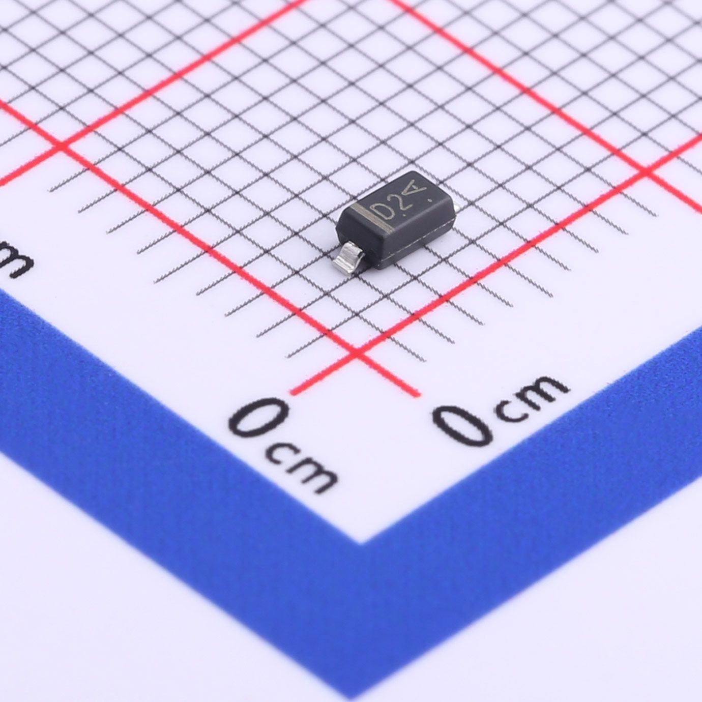
【Daily Highlight】The Voltage Regulator Diode MMSZ5227B
2026-09-30
778
Introduction:
In the vast landscape of electronic components, where precision and reliability are paramount, the MMSZ5227B Zener diode emerges as a stalwart guardian, guiding engineers and designers towards unparalleled performance and stability. With its remarkable specifications and versatile applications, the MMSZ5227B stands as a testament to precision engineering and innovation. Let's embark on a journey to unravel the intricacies of this remarkable component and explore its significance in the realm of electronic design.
Slkor Voltage Regulator Diode MMSZ5227B product photo
Key Specifications:
1. Nominal Zener Voltage (VZTyp): At the core of the MMSZ5227B lies its defining feature - a nominal Zener voltage of 3.6V. This precise voltage reference serves as a beacon of stability in voltage regulation circuits, providing a reliable reference point for maintaining consistent voltage levels across a wide range of applications. Whether in power supplies, voltage clamping circuits, or signal conditioning modules, the MMSZ5227B ensures precise and reliable operation, even in the face of fluctuating input voltages.
2. Precision (±5%): With a tolerance of ±5%, the MMSZ5227B exemplifies the epitome of precision in electronic components. This tight tolerance ensures that the Zener voltage remains within a narrow range of variation, allowing designers to achieve accurate and predictable performance in their circuits. Whether in critical applications such as precision instrumentation or high-performance audio equipment, the MMSZ5227B delivers consistent results, enabling engineers to meet the most demanding specifications with confidence.
3. Power Dissipation (PD): Despite its compact size, the MMSZ5227B boasts a robust power dissipation capability of 500mW. This impressive feature enables it to handle moderate to high power levels with ease, making it suitable for a wide range of applications where reliability and durability are essential. From voltage regulation to overvoltage protection, the MMSZ5227B offers peace of mind, ensuring reliable performance under challenging operating conditions.
4. Ultra-Low Reverse Current (Ir): A hallmark of efficiency, the MMSZ5227B showcases an ultra-low reverse current of 15nA at 1V. This minimal leakage current minimizes power losses and ensures optimal performance, particularly in low-power applications where energy efficiency is critical. Whether in battery-powered devices, portable electronics, or energy harvesting systems, the MMSZ5227B helps maximize battery life and extend the operational lifespan of electronic devices.
Slkor Zener diode MMSZ5227B specification
Applications Across Industries:
The versatility of the MMSZ5227B extends across a wide range of industries and applications, where its precision and reliability unlock new possibilities for innovation and advancement. Here are just a few examples of its notable applications:
1. Voltage Regulation: In power supplies, voltage references, and voltage divider circuits, the MMSZ5227B provides precise voltage regulation, ensuring stable and reliable operation of electronic systems across varying load conditions.
2. Signal Conditioning: In sensor interfaces, data acquisition systems, and analog signal processing circuits, the MMSZ5227B acts as a reference voltage source, enabling accurate measurement and conditioning of analog signals for precise data analysis and control.
3. Overvoltage Protection: In electronic systems susceptible to voltage transients and surges, such as automotive electronics, industrial control systems, and telecommunications equipment, the MMSZ5227B serves as a robust clamping device, protecting sensitive components from damage due to excessive voltages.
4. Battery Management: In battery charging circuits, energy harvesting systems, and portable electronics, the MMSZ5227B helps optimize power efficiency and extend battery life by providing accurate voltage regulation and minimizing power losses through its low reverse current.
Parameters of Slkor Zener diode MMSZ5227B
Conclusion:
In conclusion, the MMSZ5227B Zener diode embodies the principles of precision, reliability, and versatility in electronic design. With its remarkable specifications and wide-ranging applications, it empowers engineers and designers to achieve optimal performance and efficiency in their electronic systems. As we navigate the ever-evolving landscape of technology, let the MMSZ5227B serve as a guiding light, illuminating the path towards innovation and excellence in electronic design and engineering.
What is the technology and product roadmap of Slkor?
Slkor's technology roadmap primarily focuses on power devices, TVS diodes, and other similar products. The company plans to gradually expand its product line to include ADC series products, MCUs, and other active devices. By combining active and passive components under the "SLKOR" brand, Slkor offers a range of products for customers to choose from, enhancing interaction and stickiness with end customers. This strategy strengthens bargaining power and increases competitive advantage, thus laying a solid foundation for increasing sales revenue and gross profit.
About Slkor:
Slkor has research and development offices in Busan, South Korea, Beijing, China, and Suzhou, China. Most of the wafer manufacturing and packaging and testing are carried out within China. The company employs and collaborates with individuals and organizations worldwide, with a laboratory for product performance and reliability testing and a central warehouse located at its headquarters in Shenzhen. Slkor has filed for over a hundred invention patents, offers more than 2,000 product models, and serves over ten thousand customers globally. Its products are exported to countries and regions including Europe, the Americas, Southeast Asia, and the Middle East, making it one of the rapidly growing semiconductor companies in recent years. With well-established management systems and streamlined workflows, Slkor has rapidly enhanced the brand awareness and reputation of its "SLKOR" brand through its outstanding quality and standardized services. Its product range includes three major series: diodes, transistors, and power devices, with recent introductions of new products such as Hall elements and analog devices, expanding its presence in sensors, Risc-v microcontrollers, and other product categories.
MMSZ5227BTo Product Page
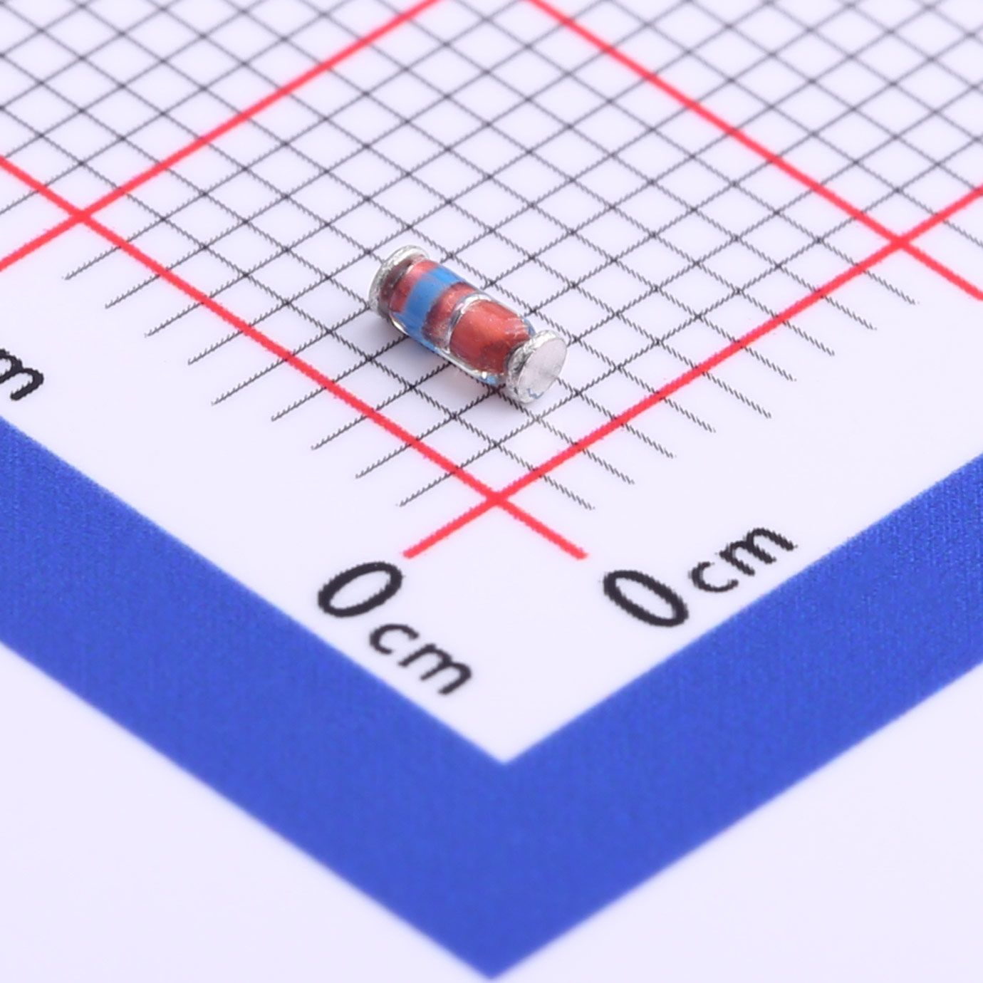
【Daily Highlight】The Voltage Regulator Diode ZMM20
2026-09-30
749
Introduction:
In the realm of electronic components, where precision and reliability are paramount, the ZMM20 Zener diode emerges as a stalwart guardian, guiding engineers and designers towards unparalleled performance and stability. With its remarkable specifications and versatile applications, the ZMM20 stands as a testament to precision engineering and innovation. Let's embark on a journey to unravel the intricacies of this remarkable component and explore its significance in the realm of electronic design.
Slkor Voltage Regulator Diode ZMM20 product photo
Key Specifications:
1. Nominal Zener Voltage (VZTyp): At the heart of the ZMM20 lies its defining feature - a nominal Zener voltage of 20V. This precise voltage reference serves as a beacon of stability in voltage regulation circuits, providing a reliable reference point for maintaining consistent voltage levels across a wide range of applications. Whether in power supplies, voltage clamping circuits, or signal conditioning modules, the ZMM20 ensures precise and reliable operation, even in the face of fluctuating input voltages.
2. Power Dissipation (PD): Despite its compact size, the ZMM20 boasts a robust power dissipation capability of 500mW. This impressive feature enables it to handle moderate to high power levels with ease, making it suitable for a wide range of applications where reliability and durability are essential. From voltage regulation to overvoltage protection, the ZMM20 offers peace of mind, ensuring reliable performance under challenging operating conditions.
3. Ultra-Low Reverse Current (Ir): A hallmark of efficiency, the ZMM20 showcases an ultra-low reverse current of 100nA at 15V. This minimal leakage current minimizes power losses and ensures optimal performance, particularly in low-power applications where energy efficiency is critical. Whether in battery-powered devices, portable electronics, or energy harvesting systems, the ZMM20 helps maximize battery life and extend the operational lifespan of electronic devices.
Slkor Zener diode ZMM20 specification
Applications Across Industries:
The versatility of the ZMM20 extends across a wide range of industries and applications, where its precision and reliability unlock new possibilities for innovation and advancement. Here are just a few examples of its notable applications:
1. Voltage Regulation: In power supplies, voltage references, and voltage divider circuits, the ZMM20 provides precise voltage regulation, ensuring stable and reliable operation of electronic systems across varying load conditions.
2. Signal Conditioning: In sensor interfaces, data acquisition systems, and analog signal processing circuits, the ZMM20 acts as a reference voltage source, enabling accurate measurement and conditioning of analog signals for precise data analysis and control.
3. Overvoltage Protection: In electronic systems susceptible to voltage transients and surges, such as automotive electronics, industrial control systems, and telecommunications equipment, the ZMM20 serves as a robust clamping device, protecting sensitive components from damage due to excessive voltages.
4. Battery Management: In battery charging circuits, energy harvesting systems, and portable electronics, the ZMM20 helps optimize power efficiency and extend battery life by providing accurate voltage regulation and minimizing power losses through its low reverse current.
Parameters of Slkor Zener diode ZMM20
Conclusion:
In conclusion, the ZMM20 Zener diode embodies the principles of precision, reliability, and versatility in electronic design. With its remarkable specifications and wide-ranging applications, it empowers engineers and designers to achieve optimal performance and efficiency in their electronic systems. As we navigate the ever-evolving landscape of technology, let the ZMM20 serve as a guiding light, illuminating the path towards innovation and excellence in electronic design and engineering.
What is the technology and product roadmap of Slkor?
Slkor's technology roadmap primarily focuses on power devices, TVS diodes, and other similar products. The company plans to gradually expand its product line to include ADC series products, MCUs, and other active devices. By combining active and passive components under the "SLKOR" brand, Slkor offers a range of products for customers to choose from, enhancing interaction and stickiness with end customers. This strategy strengthens bargaining power and increases competitive advantage, thus laying a solid foundation for increasing sales revenue and gross profit.
About Slkor:
Slkor has research and development offices in Busan, South Korea, Beijing, China, and Suzhou, China. Most of the wafer manufacturing and packaging and testing are carried out within China. The company employs and collaborates with individuals and organizations worldwide, with a laboratory for product performance and reliability testing and a central warehouse located at its headquarters in Shenzhen. Slkor has filed for over a hundred invention patents, offers more than 2,000 product models, and serves over ten thousand customers globally. Its products are exported to countries and regions including Europe, the Americas, Southeast Asia, and the Middle East, making it one of the rapidly growing semiconductor companies in recent years. With well-established management systems and streamlined workflows, Slkor has rapidly enhanced the brand awareness and reputation of its "SLKOR" brand through its outstanding quality and standardized services. Its product range includes three major series: diodes, transistors, and power devices, with recent introductions of new products such as Hall elements and analog devices, expanding its presence in sensors, Risc-v microcontrollers, and other product categories.
ZMM20To Product Page
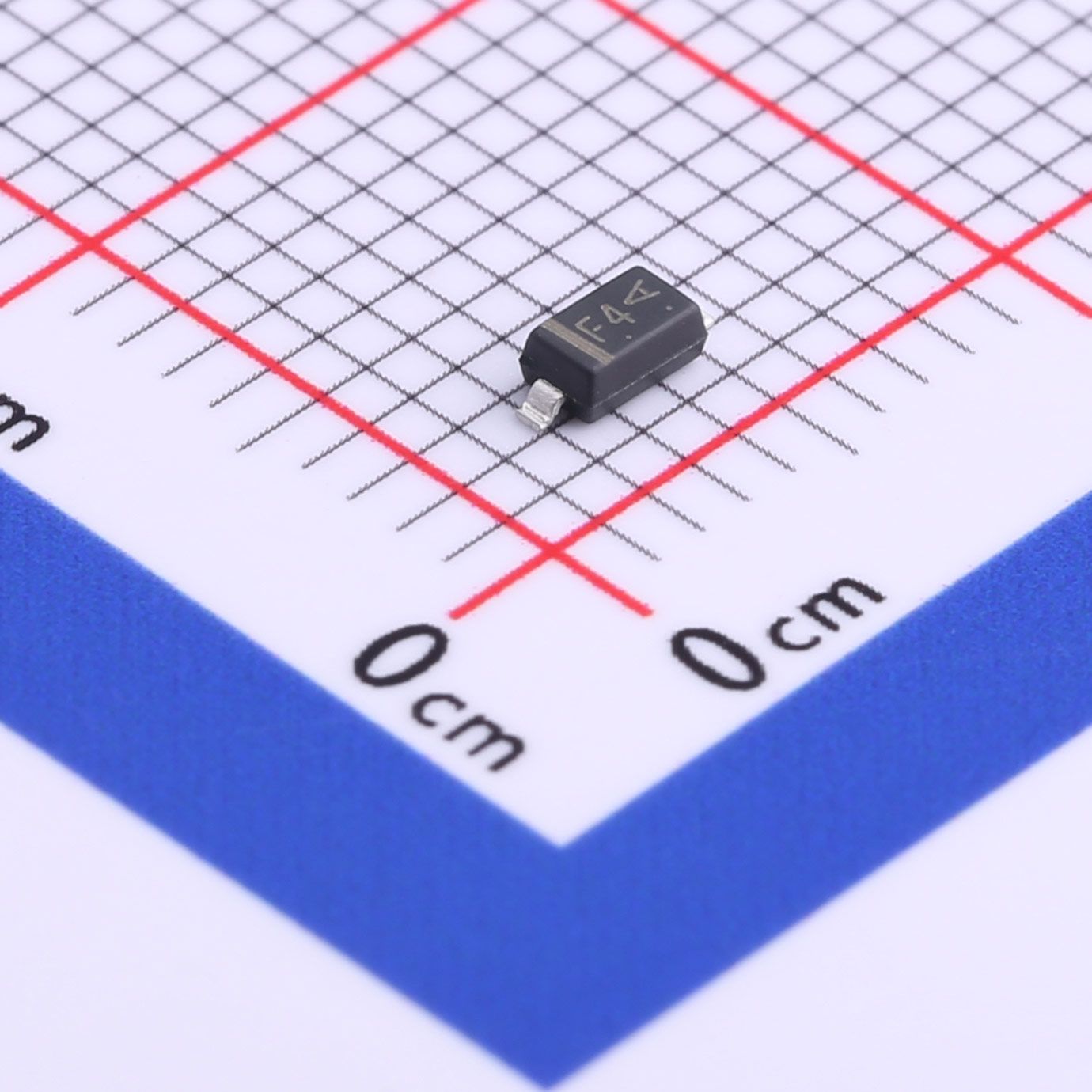
【Daily Highlight】The Voltage Regulator Diode MMSZ5239B
2026-09-30
761
Introduction:
In the intricate world of electronics, where stability and accuracy are paramount, components like the MMSZ5239B Zener diode emerge as essential tools for engineers and designers. This article aims to delve into the specifications, features, and applications of the MMSZ5239B, highlighting its crucial role in modern electronic circuits.
Slkor Voltage Regulator Diode MMSZ5239B product photo
Understanding the MMSZ5239B:
The MMSZ5239B Zener diode, distinguished by its alphanumeric identifier, embodies critical attributes necessary for voltage regulation in electronic systems. Let's explore its specifications:
Model Number: The "MMSZ" prefix indicates its classification as a Zener diode. "5239" signifies a maximum reverse working voltage of 5.6V, encompassing the specified range of 5.28V to 6.12V. The "B" suffix denotes the specific model within the MMSZ series.
VZTyp-9.1V: This parameter denotes the typical Zener voltage of the diode. Under standard conditions, typically around 25°C, the MMSZ5239B maintains a Zener voltage of approximately 9.1V. This characteristic ensures precise voltage regulation, crucial for various electronic applications.
Precision: ±5%: The precision of the MMSZ5239B Zener diode is specified at ±5%. This indicates the tolerance range within which the actual Zener voltage may vary from the typical value of 9.1V, ensuring consistent performance across different manufacturing batches.
PD 500mW: The maximum power dissipation of the MMSZ5239B is rated at 500 milliwatts. This specification highlights the diode's capability to handle significant power levels while maintaining operational integrity, making it suitable for a wide range of electronic environments.
Ir 3nA@6.5V: Reverse leakage current is a crucial parameter for Zener diodes, indicating the amount of current that flows in the reverse direction when a specific reverse voltage is applied. At a reverse voltage of 6.5V, the MMSZ5239B exhibits a reverse leakage current of 3 nanoamps, ensuring minimal power wastage and optimizing overall efficiency.
Slkor Zener diode MMSZ5239B specification
Features and Advantages:
The MMSZ5239B Zener diode offers several features that underscore its versatility and utility in electronic designs:
Precise Voltage Regulation: With its stable Zener voltage characteristic and a precision of ±5%, the MMSZ5239B facilitates precise voltage regulation, essential for applications requiring consistent voltage levels across diverse operating conditions.
Compact Design: Housed in a space-efficient SOD-123 form factor, the MMSZ5239B occupies minimal board space, making it ideal for compact electronic devices and applications with strict size constraints.
High Power Dissipation: With a maximum power dissipation of 500mW, the diode can handle substantial power levels, ensuring reliability and longevity in demanding electronic environments.
Ultra-Low Reverse Leakage: The diode's ultra-low reverse leakage current of 3 nanoamps minimizes power dissipation, enhancing energy efficiency and extending battery life in portable electronic devices and low-power applications.
Parameters of Slkor Zener diode MMSZ5239B
Applications:
The MMSZ5239B Zener diode finds broad application across diverse electronic circuits and systems, including but not limited to:
Voltage Regulation Circuits: From precision voltage references to voltage limiters, the MMSZ5239B enables accurate voltage control, ensuring stable and reliable operation of electronic systems in industrial and consumer applications.
Power Supply Units: Integrated within power management circuits, the diode aids in voltage stabilization and transient suppression, protecting sensitive components against voltage spikes and fluctuations.
Signal Conditioning Circuits: In analog signal processing applications, the MMSZ5239B serves as a reference voltage source, enabling precise signal conditioning and amplification for optimal system performance.
Telecommunications Equipment: From communication transceivers to networking devices, the MMSZ5239B contributes to the efficiency and reliability of telecommunications equipment, ensuring consistent voltage levels for seamless data transmission.
Conclusion:
In conclusion, the MMSZ5239B Zener diode embodies precision and reliability in voltage regulation, offering engineers and designers a versatile solution for a wide range of electronic applications. With its stable characteristics, compact design, and superior performance specifications, the MMSZ5239B continues to be a cornerstone of modern electronic designs, driving innovation and advancing technology across various industries.
What is the technology and product roadmap of Slkor?
Slkor's technology roadmap primarily focuses on power devices, TVS diodes, and other similar products. The company plans to gradually expand its product line to include ADC series products, MCUs, and other active devices. By combining active and passive components under the "SLKOR" brand, Slkor offers a range of products for customers to choose from, enhancing interaction and stickiness with end customers. This strategy strengthens bargaining power and increases competitive advantage, thus laying a solid foundation for increasing sales revenue and gross profit.
About Slkor:
Slkor has research and development offices in Busan, South Korea, Beijing, China, and Suzhou, China. Most of the wafer manufacturing and packaging and testing are carried out within China. The company employs and collaborates with individuals and organizations worldwide, with a laboratory for product performance and reliability testing and a central warehouse located at its headquarters in Shenzhen. Slkor has filed for over a hundred invention patents, offers more than 2,000 product models, and serves over ten thousand customers globally. Its products are exported to countries and regions including Europe, the Americas, Southeast Asia, and the Middle East, making it one of the rapidly growing semiconductor companies in recent years. With well-established management systems and streamlined workflows, Slkor has rapidly enhanced the brand awareness and reputation of its "SLKOR" brand through its outstanding quality and standardized services. Its product range includes three major series: diodes, transistors, and power devices, with recent introductions of new products such as Hall elements and analog devices, expanding its presence in sensors, Risc-v microcontrollers, and other product categories.
MMSZ5239BTo Product Page
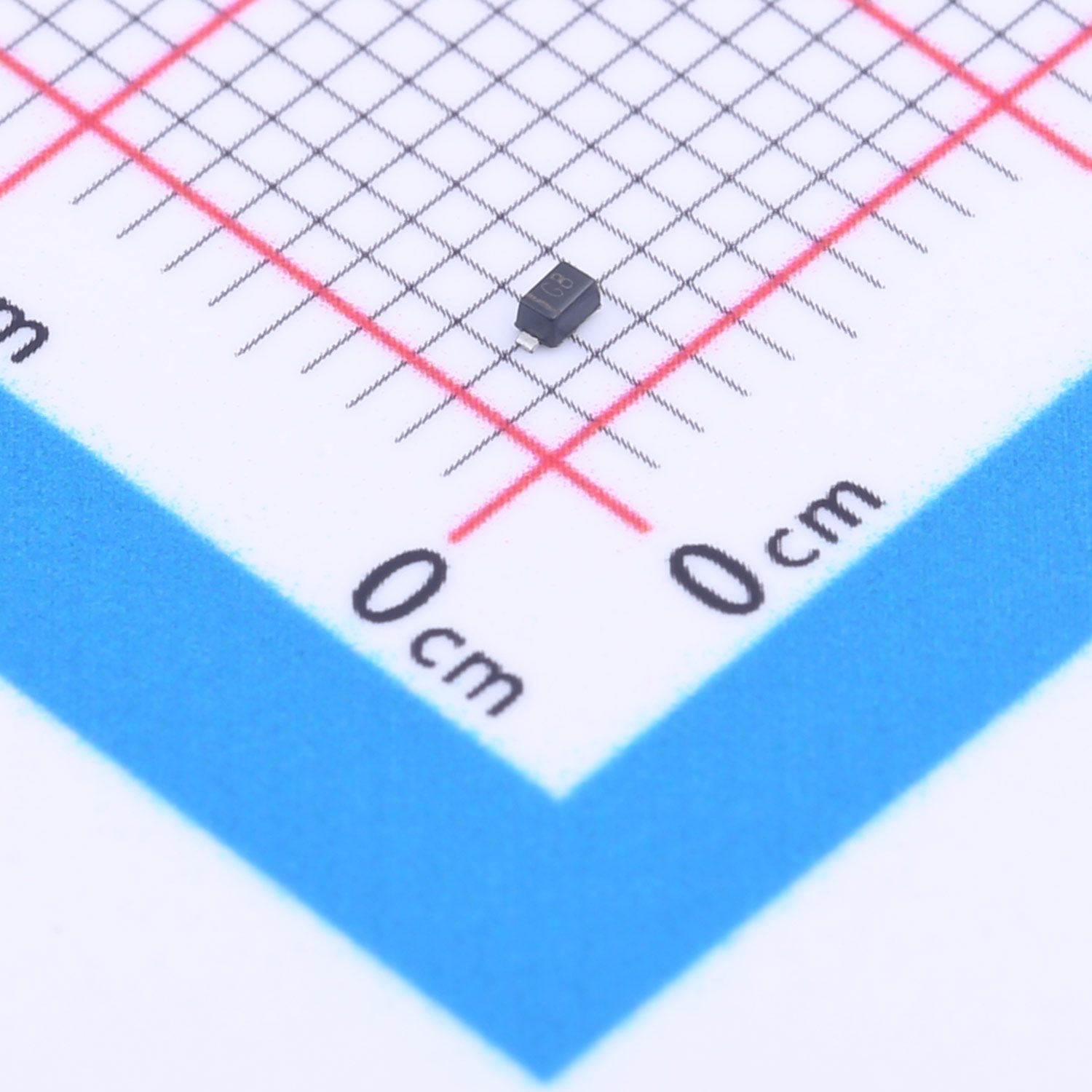
【Daily Highlight】The Voltage Regulator Diode MM5Z4V7
2026-09-30
770
Introduction:
In the dynamic realm of electronics, where stability and accuracy reign supreme, precision components like the MM5Z4V7 Zener diode emerge as indispensable assets for engineers and designers alike. This article aims to explore the specifications, features, and applications of the MM5Z4V7, shedding light on its pivotal role in modern electronic circuits.
Slkor Voltage Regulator Diode MM5Z4V7 product photo
Understanding the MM5Z4V7:
The MM5Z4V7 Zener diode, characterized by its alphanumeric identifier, embodies key attributes crucial for voltage regulation in electronic systems. Let's delve into its specifications:
Model Number: The "MM" prefix signifies its classification as a Zener diode, while "5Z" indicates a maximum reverse working voltage of 5.5V, encompassing the specified range of 4.4V to 5V. The "4V7" suffix designates the specific model within the MM5Z series, with a typical Zener voltage of 4.7V.
VZTyp-4.7V: This parameter denotes the typical Zener voltage of the diode. Under standard conditions, typically around 25°C, the MM5Z4V7 maintains a Zener voltage of approximately 4.7V. This characteristic ensures precise voltage regulation, pivotal for a myriad of electronic applications.
PD 200mW: The maximum power dissipation of the MM5Z4V7 is rated at 200 milliwatts. This specification underscores the diode's ability to handle significant power levels while maintaining operational integrity, making it well-suited for diverse electronic environments.
Ir 2μA@1V: Reverse leakage current is a critical parameter for Zener diodes, indicating the amount of current that flows in the reverse direction when a specific reverse voltage is applied. At a reverse voltage of 1V, the MM5Z4V7 exhibits a reverse leakage current of 2 microamps, ensuring minimal power wastage and optimizing overall efficiency.
Zzt 80Ω: The dynamic impedance of the MM5Z4V7, denoted by Zzt, is specified at 80 ohms. This parameter characterizes the diode's ability to maintain a stable voltage across its terminals under varying operating conditions, contributing to robust voltage regulation in electronic circuits.
Slkor Voltage Regulator Diode MM5Z4V7 specification
Features and Advantages:
The MM5Z4V7 Zener diode offers a host of features that underscore its versatility and utility in electronic designs:
Precise Voltage Regulation: With its stable Zener voltage characteristic, the MM5Z4V7 facilitates precise voltage regulation, essential for applications requiring consistent voltage levels across diverse operating conditions.
Compact Design: Packaged in a space-efficient SOD-523 form factor, the MM5Z4V7 occupies minimal board space, making it ideal for compact electronic devices and applications with stringent size constraints.
Low Reverse Leakage: The diode's low reverse leakage current ensures minimal power dissipation, enhancing energy efficiency and prolonging battery life in portable electronic devices and low-power applications.
High Dynamic Impedance: With a dynamic impedance of 80 ohms, the MM5Z4V7 exhibits robust voltage regulation capabilities, mitigating voltage fluctuations and ensuring stable performance across a wide range of operating conditions.
Parameters of Slkor Voltage Regulator Diode MM5Z4V7
Applications:
The MM5Z4V7 Zener diode finds extensive application across diverse electronic circuits and systems, including but not limited to:
Voltage Regulation Circuits: From voltage references to voltage limiters, the MM5Z4V7 facilitates precise voltage control, ensuring stable and reliable operation of electronic systems in various industrial and consumer applications.
Power Supply Units: Integrated within power management circuits, the diode aids in voltage stabilization and transient suppression, safeguarding sensitive components against voltage spikes and fluctuations.
Signal Conditioning Circuits: In analog signal processing applications, the MM5Z4V7 serves as a reference voltage source, enabling accurate signal conditioning and amplification for optimal system performance.
Automotive Electronics: From vehicle control modules to lighting systems, the MM5Z4V7 contributes to the efficiency and reliability of automotive electronics, ensuring consistent voltage levels for critical subsystems.
Conclusion:
In summary, the MM5Z4V7 Zener diode embodies precision and reliability in voltage regulation, offering engineers and designers a versatile solution for a wide array of electronic applications. With its robust specifications, compact design, and superior performance characteristics, the MM5Z4V7 continues to be a cornerstone of modern electronic designs, driving innovation and advancing technology across industries.
What is the technology and product roadmap of Slkor?
Slkor's technology roadmap primarily focuses on power devices, TVS diodes, and other similar products. The company plans to gradually expand its product line to include ADC series products, MCUs, and other active devices. By combining active and passive components under the "SLKOR" brand, Slkor offers a range of products for customers to choose from, enhancing interaction and stickiness with end customers. This strategy strengthens bargaining power and increases competitive advantage, thus laying a solid foundation for increasing sales revenue and gross profit.
About Slkor:
Slkor has research and development offices in Busan, South Korea, Beijing, China, and Suzhou, China. Most of the wafer manufacturing and packaging and testing are carried out within China. The company employs and collaborates with individuals and organizations worldwide, with a laboratory for product performance and reliability testing and a central warehouse located at its headquarters in Shenzhen. Slkor has filed for over a hundred invention patents, offers more than 2,000 product models, and serves over ten thousand customers globally. Its products are exported to countries and regions including Europe, the Americas, Southeast Asia, and the Middle East, making it one of the rapidly growing semiconductor companies in recent years. With well-established management systems and streamlined workflows, Slkor has rapidly enhanced the brand awareness and reputation of its "SLKOR" brand through its outstanding quality and standardized services. Its product range includes three major series: diodes, transistors, and power devices, with recent introductions of new products such as Hall elements and analog devices, expanding its presence in sensors, Risc-v microcontrollers, and other product categories.
MM5Z4V7To Product Page
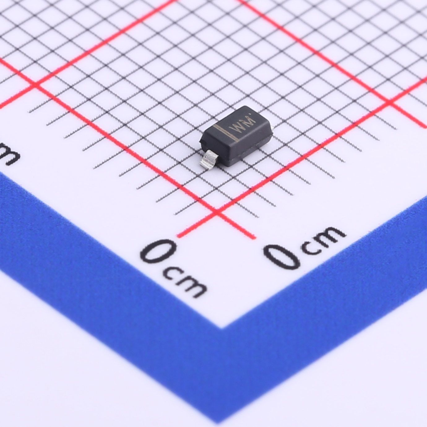
【Daily Highlight】The Voltage Regulator Diode BZT52C22
2026-09-30
751
Introduction:
In the intricate world of electronics, where stability and reliability are paramount, precision components such as the BZT52C22 Zener diode stand as indispensable tools for engineers and designers. This article delves into the specifications, features, and applications of the BZT52C22, shedding light on its significance in modern electronic designs.
Slkor Voltage Regulator Diode BZT52C22 product photo
Understanding the BZT52C22:
The BZT52C22 Zener diode, with its alphanumeric nomenclature, embodies key characteristics crucial for voltage regulation in electronic systems. Let's break down its specifications:
Model Number: The "BZT" prefix signifies its classification as a Zener diode. The "52" designation denotes a maximum reverse working voltage of 5.2V, while the "C22" suffix represents its specific model within the BZT52C series.
VZTyp-22V: This parameter denotes the typical Zener voltage of the diode. At standard conditions, typically around 25°C, the BZT52C22 maintains a Zener voltage of approximately 22V. This characteristic ensures a consistent voltage across its terminals, critical for various electronic applications.
PD 500mW: The maximum power dissipation of the BZT52C22 is rated at 500 milliwatts. This specification underscores the diode's ability to handle substantial power levels without compromising its functionality, making it suitable for diverse operational environments.
Ir 100nA@15.4V: Reverse leakage current is a crucial parameter for Zener diodes, indicating the amount of current that flows in the reverse direction when a specific reverse voltage is applied. At a reverse voltage of 15.4V, the BZT52C22 exhibits a reverse leakage current of 100 nanoamps, ensuring minimal power wastage and enhancing overall efficiency.
Slkor Voltage Regulator Diode BZT52C22 specification
Features and Advantages:
The BZT52C22 Zener diode boasts several features that contribute to its widespread adoption and utility in electronic circuits:
Precision Voltage Regulation: With its stable Zener voltage characteristic, the BZT52C22 facilitates precise voltage regulation, essential for applications requiring consistent voltage levels.
Compact Form Factor: Packaged in SOD-123 form, the BZT52C22 offers a compact footprint, making it suitable for space-constrained designs without compromising performance.
Low Reverse Leakage: The diode's low reverse leakage current ensures minimal power dissipation, enhancing energy efficiency and prolonging battery life in portable electronic devices.
Wide Operating Temperature Range: Designed to operate reliably across a broad temperature range, the BZT52C22 maintains its performance integrity under varying environmental conditions, catering to diverse application scenarios.
Parameters of Slkor Voltage Regulator Diode BZT52C22
Applications:
The versatility and reliability of the BZT52C22 Zener diode render it indispensable across a spectrum of electronic applications, including but not limited to:
Voltage Regulation Circuits: From voltage stabilizers to voltage reference circuits, the BZT52C22 ensures consistent voltage output, vital for system stability and performance optimization.
Power Management Systems: In conjunction with other components, the diode facilitates efficient power distribution and management, safeguarding sensitive electronic components against voltage fluctuations.
Analog Circuitry: The BZT52C22 finds utility in analog signal processing circuits, where precise voltage references are essential for accurate signal conditioning and processing.
Consumer Electronics: From smartphones to household appliances, the BZT52C22 contributes to the seamless operation of various consumer electronic devices, enhancing user experience and reliability.
Conclusion:
In summary, the BZT52C22 Zener diode epitomizes precision and reliability in voltage regulation, offering engineers and designers a versatile solution for diverse electronic applications. With its robust specifications, compact design, and broad applicability, the BZT52C22 continues to serve as a cornerstone of modern electronic designs, empowering innovation across industries and driving technological advancement forward.
What is the technology and product roadmap of Slkor?
Slkor's technology roadmap primarily focuses on power devices, TVS diodes, and other similar products. The company plans to gradually expand its product line to include ADC series products, MCUs, and other active devices. By combining active and passive components under the "SLKOR" brand, Slkor offers a range of products for customers to choose from, enhancing interaction and stickiness with end customers. This strategy strengthens bargaining power and increases competitive advantage, thus laying a solid foundation for increasing sales revenue and gross profit.
About Slkor:
Slkor has research and development offices in Busan, South Korea, Beijing, China, and Suzhou, China. Most of the wafer manufacturing and packaging and testing are carried out within China. The company employs and collaborates with individuals and organizations worldwide, with a laboratory for product performance and reliability testing and a central warehouse located at its headquarters in Shenzhen. Slkor has filed for over a hundred invention patents, offers more than 2,000 product models, and serves over ten thousand customers globally. Its products are exported to countries and regions including Europe, the Americas, Southeast Asia, and the Middle East, making it one of the rapidly growing semiconductor companies in recent years. With well-established management systems and streamlined workflows, Slkor has rapidly enhanced the brand awareness and reputation of its "SLKOR" brand through its outstanding quality and standardized services. Its product range includes three major series: diodes, transistors, and power devices, with recent introductions of new products such as Hall elements and analog devices, expanding its presence in sensors, Risc-v microcontrollers, and other product categories.
BZT52C22To Product Page
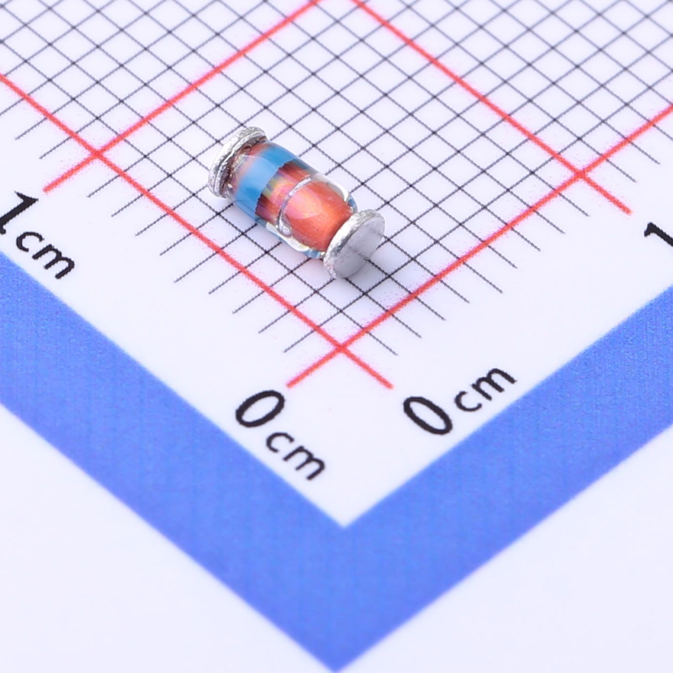
【Daily Highlight】The Voltage Regulator Diode ZM4734A
2026-09-30
757
Introduction:
Zener diodes are essential components in electronic systems, providing voltage regulation and protection against voltage fluctuations. One such diode, the ZM4734A, is known for its excellent precision and high power handling capabilities. In this article, we will delve into the key parameters of the ZM4734A, including its typical voltage, precision, power dissipation, current leakage, and impedance characteristics.
Slkor Voltage Regulator Diode ZM4734A product photo
ZM4734A Overview:The ZM4734A is a popular Zener diode widely used in various applications, including voltage regulation, voltage clamping, and transient suppression. It is designed to maintain a constant voltage across its terminals, even under varying input voltages or load conditions.
Slkor Voltage Regulator Diode ZM4734A specification
Typical Voltage (VZTyp):
The ZM4734A has a typical Zener voltage (VZTyp) of 5.6V. This value represents the voltage at which the diode starts regulating the current passing through it. It ensures that the voltage across the diode remains constant, offering stability in the circuit.
Precision (±5%):
Precision is an important parameter for Zener diodes. The ZM4734A exhibits a precision of ±5%, which means that the Zener voltage can deviate by a maximum of 5% from the specified value. This level of precision ensures accurate voltage regulation in a wide range of applications.
Power Dissipation (PD):
With a power dissipation rating of 1W, the ZM4734A can handle substantial power without getting damaged or overheated. This capability makes it suitable for applications that require high power dissipation, providing reliable performance under challenging conditions.
Current Leakage (Ir):
The ZM4734A boasts low current leakage, with a maximum leakage current (Ir) of 10μA at 2V. This attribute ensures minimal power loss and enhances the overall efficiency of the circuit.
Impedance (Zzt):
Impedance (Zzt) is another critical characteristic of Zener diodes. The ZM4734A exhibits an impedance of 5Ω, representing the equivalent series resistance of the diode. Lower impedance allows for better voltage regulation and reduced power dissipation.
Parameters of Slkor Voltage Regulator Diode ZM4734A
Conclusion:The ZM4734A Zener diode offers precise voltage regulation, high power handling capability, and low current leakage. With its typical voltage of 5.6V, ±5% precision, 1W power dissipation, 10μA current leakage at 2V, and 5Ω impedance, it proves to be an excellent choice for various electronic applications. Whether it's stabilizing voltage levels or protecting sensitive components from voltage spikes, the ZM4734A delivers reliable performance and ensures the integrity of electronic systems.
Note: The information provided is based on the given parameters. It's always recommended to refer to the datasheet and consult the manufacturer for specific details and guidelines regarding the ZM4734A Zener diode.
What is the technology and product roadmap of Slkor?
Slkor's technology roadmap primarily focuses on power devices, TVS diodes, and other similar products. The company plans to gradually expand its product line to include ADC series products, MCUs, and other active devices. By combining active and passive components under the "SLKOR" brand, Slkor offers a range of products for customers to choose from, enhancing interaction and stickiness with end customers. This strategy strengthens bargaining power and increases competitive advantage, thus laying a solid foundation for increasing sales revenue and gross profit.
About Slkor:Slkor has research and development offices in Busan, South Korea, Beijing, China, and Suzhou, China. Most of the wafer manufacturing and packaging and testing are carried out within China. The company employs and collaborates with individuals and organizations worldwide, with a laboratory for product performance and reliability testing and a central warehouse located at its headquarters in Shenzhen. Slkor has filed for over a hundred invention patents, offers more than 2,000 product models, and serves over ten thousand customers globally. Its products are exported to countries and regions including Europe, the Americas, Southeast Asia, and the Middle East, making it one of the rapidly growing semiconductor companies in recent years. With well-established management systems and streamlined workflows, Slkor has rapidly enhanced the brand awareness and reputation of its "SLKOR" brand through its outstanding quality and standardized services. Its product range includes three major series: diodes, transistors, and power devices, with recent introductions of new products such as Hall elements and analog devices, expanding its presence in sensors, Risc-v microcontrollers, and other product categories.
ZM4734ATo Product Page
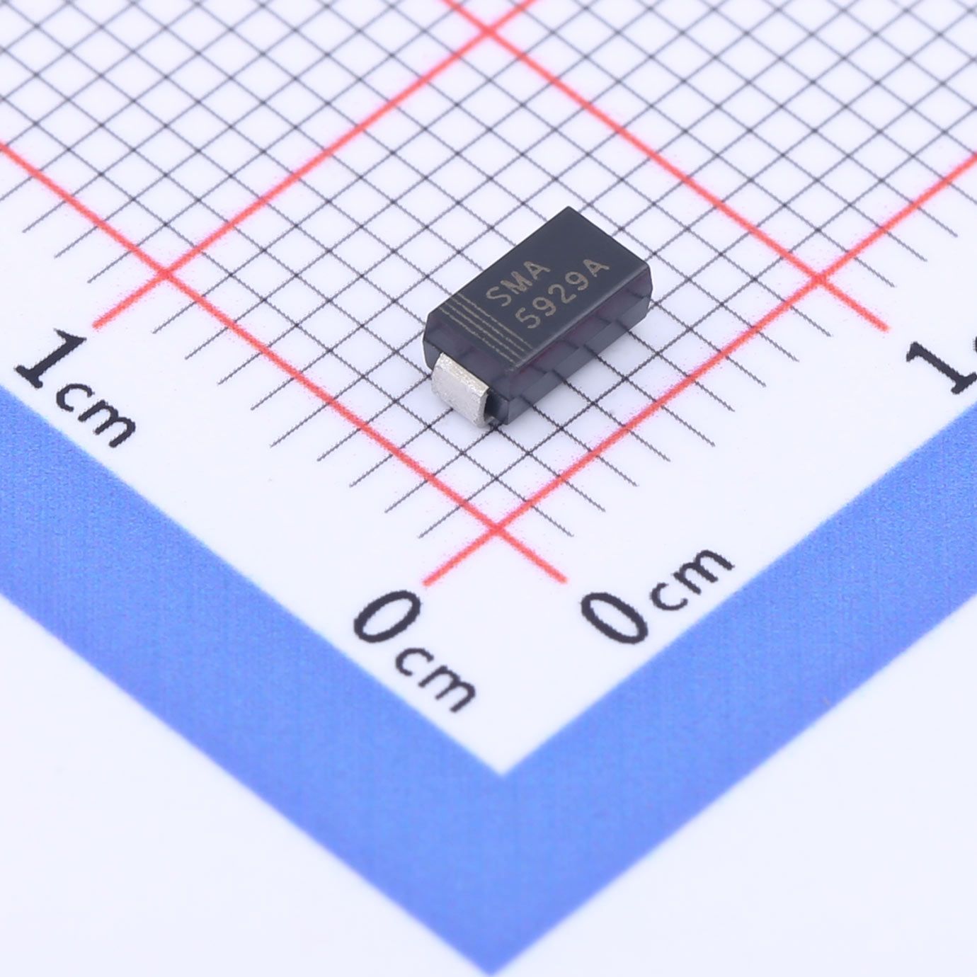
【Daily Highlight】The Voltage Regulator Diode 1SMA5929A
2026-09-30
750
Introduction:Zener diodes play a pivotal role in modern electronic circuits by ensuring stable voltage levels and safeguarding sensitive components from voltage variations. Among these, the 1SMA5929A Zener diode stands out for its robust performance and versatile applications. This article will explore the key specifications of the 1SMA5929A, including its typical voltage, precision, power dissipation, and current leakage characteristics, shedding light on its significance in electronic design.
Slkor Voltage Regulator Diode 1SMA5929A product photo
1SMA5929A Overview:The 1SMA5929A is a highly regarded Zener diode renowned for its ability to regulate voltage effectively across diverse electronic systems. Designed to provide precise voltage control and protection against voltage fluctuations, this diode finds extensive use in voltage stabilization, voltage clamping, and transient suppression applications.
Slkor Voltage Regulator Diode 1SMA5929A specification
Typical Voltage (VZTyp):
At the heart of the 1SMA5929A lies its typical Zener voltage (VZTyp) of 15V. This value signifies the voltage level at which the diode commences its voltage regulation function, ensuring that the voltage remains constant despite fluctuations in the input voltage or variations in the load.
Precision (±5%):
Precision is a crucial factor in Zener diodes, determining the accuracy of voltage regulation. The 1SMA5929A boasts a precision rating of ±5%, indicating that the actual Zener voltage may deviate by a maximum of 5% from the specified value. This high level of precision ensures dependable performance across a wide range of operating conditions.
Power Dissipation (PD):
With a power dissipation rating of 1.5W, the 1SMA5929A demonstrates exceptional capability in dissipating heat while maintaining stable voltage regulation. This robust power handling capacity makes it suitable for demanding applications where efficient heat dissipation is essential for reliable operation.
Current Leakage (Ir):
The 1SMA5929A features minimal current leakage, with a maximum leakage current (Ir) of 1μA. Low current leakage ensures minimal power wastage and enhances the overall efficiency of the circuit, making the diode an ideal choice for power-sensitive applications.
Parameters of Slkor Voltage Regulator Diode 1SMA5929A
Conclusion:The 1SMA5929A Zener diode emerges as a reliable solution for voltage regulation and transient protection in electronic circuits. With its typical voltage of 15V, ±5% precision, 1.5W power dissipation capability, and low current leakage of 1μA, it offers superior performance across a spectrum of applications. Whether it's stabilizing voltage levels in power supplies, protecting sensitive components from voltage spikes, or ensuring the integrity of communication systems, the 1SMA5929A proves to be an indispensable component in modern electronics.
Note: While the information provided is based on the given parameters, users are advised to refer to the datasheet and consult the manufacturer for detailed specifications and application guidelines pertaining to the 1SMA5929A Zener diode.
What is the technology and product roadmap of Slkor?
Slkor's technology roadmap primarily focuses on power devices, TVS diodes, and other similar products. The company plans to gradually expand its product line to include ADC series products, MCUs, and other active devices. By combining active and passive components under the "SLKOR" brand, Slkor offers a range of products for customers to choose from, enhancing interaction and stickiness with end customers. This strategy strengthens bargaining power and increases competitive advantage, thus laying a solid foundation for increasing sales revenue and gross profit.
About Slkor:
Slkor has research and development offices in Busan, South Korea, Beijing, China, and Suzhou, China. Most of the wafer manufacturing and packaging and testing are carried out within China. The company employs and collaborates with individuals and organizations worldwide, with a laboratory for product performance and reliability testing and a central warehouse located at its headquarters in Shenzhen. Slkor has filed for over a hundred invention patents, offers more than 2,000 product models, and serves over ten thousand customers globally. Its products are exported to countries and regions including Europe, the Americas, Southeast Asia, and the Middle East, making it one of the rapidly growing semiconductor companies in recent years. With well-established management systems and streamlined workflows, Slkor has rapidly enhanced the brand awareness and reputation of its "SLKOR" brand through its outstanding quality and standardized services. Its product range includes three major series: diodes, transistors, and power devices, with recent introductions of new products such as Hall elements and analog devices, expanding its presence in sensors, Risc-v microcontrollers, and other product categories.
1SMA5929ATo Product Page
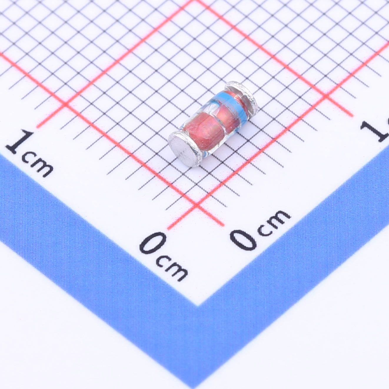
【Daily Highlight】The Voltage Regulator Diode ZM4747A
2026-09-30
585
Introduction:
Zener diodes are essential components in electronic circuits, providing voltage regulation and protection against voltage fluctuations. The ZM4747A Zener diode is a popular choice among engineers due to its high precision, robust power handling capabilities, and low current leakage. This article will explore the key characteristics of the ZM4747A, including its typical voltage, precision, power dissipation, current leakage, and impedance, highlighting its significance in modern electronic design.
Slkor Voltage Regulator Diode ZM4747A product photo
ZM4747A Overview:The ZM4747A is a well-known Zener diode that regulates voltage by maintaining a constant voltage across its terminals, despite variations in input voltage or load conditions. It is widely used in various applications, including voltage regulation, voltage clamping, and transient suppression.
Slkor Voltage Regulator Diode ZM4747A specification
Typical Voltage (VZTyp):
The ZM4747A has a typical Zener voltage (VZTyp) of 20V. This value represents the voltage at which the diode starts regulating the current passing through it, ensuring a stable voltage output despite changes in the input voltage or load conditions.
Precision (±5%):
Precision is an important parameter for Zener diodes, as it determines the accuracy of voltage regulation. The ZM4747A has a precision rating of ±5%, meaning the actual Zener voltage may deviate by a maximum of 5% from the specified value. This high level of precision ensures accurate voltage regulation across a wide range of applications.
Power Dissipation (PD):
With a power dissipation rating of 1W, the ZM4747A can handle substantial power without getting damaged or overheated. This capability makes it suitable for applications that require high power dissipation, providing reliable performance even under challenging conditions.
Current Leakage (Ir):
The ZM4747A exhibits low current leakage, with a maximum leakage current (Ir) of 5μA at 15.2V. This attribute ensures minimal power loss and enhances the overall efficiency of the circuit, making it an ideal choice for power-sensitive applications.
Impedance (Zzt):
Impedance (Zzt) is another critical characteristic of Zener diodes, representing the equivalent series resistance of the diode. The ZM4747A features an impedance of 22Ω, which is relatively low compared to other Zener diodes. Lower impedance allows for better voltage regulation and reduced power dissipation, making it an excellent choice for voltage stabilization in sensitive electronic systems.
Parameters of Slkor Voltage Regulator Diode ZM4747A
Conclusion:The ZM4747A Zener diode offers high precision, robust power handling capability, and low current leakage, making it an ideal choice for voltage regulation and transient protection in electronic circuits. With its typical voltage of 20V, ±5% precision, 1W power dissipation capability, 5μA current leakage at 15.2V, and 22Ω impedance, it proves to be an indispensable component in modern electronic design. Whether it's stabilizing voltage levels in power supplies, protecting sensitive components from voltage spikes, or ensuring the stability of communication systems, the ZM4747A delivers reliable performance and ensures the integrity of electronic systems.
Note: Users are advised to refer to the datasheet and consult the manufacturer for detailed specifications and application guidelines pertaining to the ZM4747A Zener diode.
What is the technology and product roadmap of Slkor?
Slkor's technology roadmap primarily focuses on power devices, TVS diodes, and other similar products. The company plans to gradually expand its product line to include ADC series products, MCUs, and other active devices. By combining active and passive components under the "SLKOR" brand, Slkor offers a range of products for customers to choose from, enhancing interaction and stickiness with end customers. This strategy strengthens bargaining power and increases competitive advantage, thus laying a solid foundation for increasing sales revenue and gross profit.
About Slkor:
Slkor has research and development offices in Busan, South Korea, Beijing, China, and Suzhou, China. Most of the wafer manufacturing and packaging and testing are carried out within China. The company employs and collaborates with individuals and organizations worldwide, with a laboratory for product performance and reliability testing and a central warehouse located at its headquarters in Shenzhen. Slkor has filed for over a hundred invention patents, offers more than 2,000 product models, and serves over ten thousand customers globally. Its products are exported to countries and regions including Europe, the Americas, Southeast Asia, and the Middle East, making it one of the rapidly growing semiconductor companies in recent years. With well-established management systems and streamlined workflows, Slkor has rapidly enhanced the brand awareness and reputation of its "SLKOR" brand through its outstanding quality and standardized services. Its product range includes three major series: diodes, transistors, and power devices, with recent introductions of new products such as Hall elements and analog devices, expanding its presence in sensors, Risc-v microcontrollers, and other product categories.
ZM4747ATo Product Page
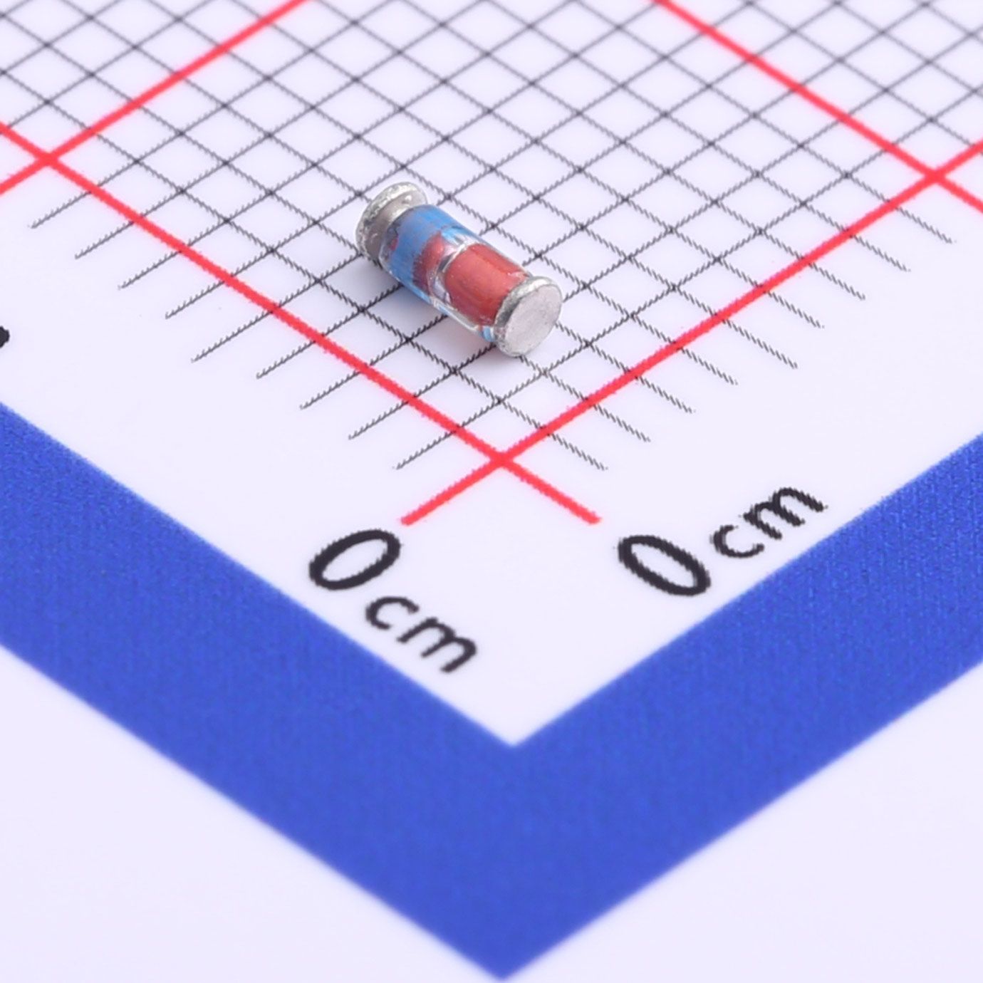
【Daily Highlight】The Voltage Regulator Diode ZMM9V1
2026-09-30
519
Introduction:
Zener diodes play a crucial role in modern electronics, providing precise voltage regulation and protection against voltage fluctuations. The ZMM9V1 Zener diode is a highly regarded component known for its precision, power dissipation capability, and minimal current leakage. This article aims to delve into the key specifications of the ZMM9V1, including its typical voltage, power dissipation, current leakage, and their significance in electronic circuit design.
Slkor Voltage Regulator Diode ZMM9V1 product photo
ZMM9V1 Overview:The ZMM9V1 Zener diode serves as a dependable voltage regulator, maintaining a constant voltage across its terminals, irrespective of variations in input voltage or load conditions. It finds widespread application in voltage stabilization, voltage clamping, and transient suppression, making it an essential component in electronic designs.
Slkor Zener diode ZMM9V1 specification
Typical Voltage (VZTyp):
At the heart of the ZMM9V1 lies its typical Zener voltage (VZTyp) of 9.1V. This characteristic denotes the voltage at which the diode initiates the regulation of current flow, ensuring a stable voltage output despite fluctuations in the input voltage or varying load conditions.
Power Dissipation (PD):
The ZMM9V1 exhibits a power dissipation rating of 500mW, indicating its ability to dissipate heat efficiently while maintaining stable voltage regulation. This feature makes it suitable for applications where heat dissipation is critical, ensuring reliable performance under diverse operating conditions.
Current Leakage (Ir):
The ZMM9V1 showcases minimal current leakage, with a maximum leakage current (Ir) of 100nA at 6.8V. Low current leakage minimizes power loss and enhances circuit efficiency, making the diode an ideal choice for power-sensitive applications where energy conservation is paramount.
Parameters of Slkor Zener diode ZMM9V1
Conclusion:The ZMM9V1 Zener diode emerges as a precision voltage regulator, offering stable voltage regulation, robust power dissipation capability, and minimal current leakage. With its typical voltage of 9.1V, 500mW power dissipation rating, and 100nA current leakage at 6.8V, it proves to be an indispensable component in modern electronic circuits. Whether it's stabilizing voltage levels in power supplies, safeguarding sensitive components from voltage spikes, or ensuring the integrity of communication systems, the ZMM9V1 delivers reliable performance and plays a pivotal role in maintaining the stability and efficiency of electronic systems.
Note: For comprehensive specifications and application guidelines pertaining to the ZMM9V1 Zener diode, users are advised to refer to the datasheet and consult the manufacturer.
What is the technology and product roadmap of Slkor?
Slkor's technology roadmap primarily focuses on power devices, TVS diodes, and other similar products. The company plans to gradually expand its product line to include ADC series products, MCUs, and other active devices. By combining active and passive components under the "SLKOR" brand, Slkor offers a range of products for customers to choose from, enhancing interaction and stickiness with end customers. This strategy strengthens bargaining power and increases competitive advantage, thus laying a solid foundation for increasing sales revenue and gross profit.
About Slkor:
Slkor has research and development offices in Busan, South Korea, Beijing, China, and Suzhou, China. Most of the wafer manufacturing and packaging and testing are carried out within China. The company employs and collaborates with individuals and organizations worldwide, with a laboratory for product performance and reliability testing and a central warehouse located at its headquarters in Shenzhen. Slkor has filed for over a hundred invention patents, offers more than 2,000 product models, and serves over ten thousand customers globally. Its products are exported to countries and regions including Europe, the Americas, Southeast Asia, and the Middle East, making it one of the rapidly growing semiconductor companies in recent years. With well-established management systems and streamlined workflows, Slkor has rapidly enhanced the brand awareness and reputation of its "SLKOR" brand through its outstanding quality and standardized services. Its product range includes three major series: diodes, transistors, and power devices, with recent introductions of new products such as Hall elements and analog devices, expanding its presence in sensors, Risc-v microcontrollers, and other product categories.
ZMM9V1To Product Page
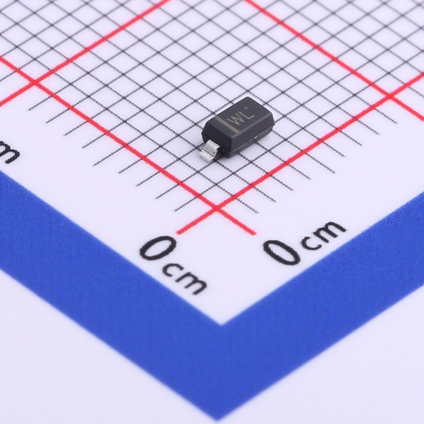
【Daily Highlight】The Voltage Regulator Diode BZT52C18
2026-09-30
521
Introduction:
The BZT52C18 is a popular Zener diode widely used in electronic circuits for voltage regulation and protection. With its specific characteristics, such as a breakdown voltage (VZTyp) of 18V, power dissipation (PD) of 500mW, and a low reverse current (Ir) of 100nA at 12.6V, it offers reliable performance in various applications. This article aims to provide a comprehensive overview of the BZT52C18 Zener diode, its features, working principle, and practical implementations.
Slkor Voltage Regulator Diode BZT52C18 product photo
Understanding Zener Diodes:
Zener diodes are special types of diodes designed to operate in the reverse-biased mode. They exhibit a controlled breakdown under specified conditions, allowing them to maintain a constant voltage across their terminals. This makes them ideal for voltage regulation and protection against voltage spikes.
Slkor Voltage Regulator Diode BZT52C18 specification
Features and Specifications of BZT52C18:
The BZT52C18 Zener diode possesses the following key features and specifications:
Breakdown Voltage (VZTyp): The typical breakdown voltage of the BZT52C18 is 18V. It means that when the reverse voltage across the diode reaches or exceeds 18V, it starts conducting and maintains a relatively constant voltage drop.
Power Dissipation (PD): The BZT52C18 can dissipate a maximum power of 500mW without getting damaged. It is essential to ensure that the power dissipation remains within this limit to prevent overheating and potential failure.
Low Reverse Current (Ir): The BZT52C18 exhibits a low reverse current of 100nA at 12.6V. This property ensures minimal leakage current when the diode is reverse-biased, contributing to its stability and efficiency.
Working Principle:
When the BZT52C18 Zener diode is reverse-biased below its breakdown voltage, it behaves like a regular diode with a negligible current flow. However, as the reverse voltage exceeds the breakdown voltage, the diode enters the breakdown region. In this region, it starts conducting and maintains a relatively constant voltage drop across its terminals, thus regulating the voltage.
Parameters of Slkor Voltage Regulator Diode BZT52C18
Practical Applications:
The BZT52C18 Zener diode finds extensive application in various electronic circuits, including but not limited to:
Voltage Regulation: It is commonly used as a voltage regulator to maintain a stable voltage level in power supplies, ensuring consistent performance of electronic components.
Overvoltage Protection: By diverting excessive voltage away from sensitive components, the BZT52C18 acts as a protective device, safeguarding circuits from damage caused by voltage spikes.
Voltage Reference: It can serve as a precise voltage reference in analog and digital circuits, facilitating accurate measurements and signal conditioning.
Conclusion:
The BZT52C18 Zener diode is an indispensable component in modern electronics, offering voltage regulation and protection capabilities. Its breakdown voltage of 18V, power dissipation of 500mW, and low reverse current of 100nA at 12.6V make it a reliable choice for a wide range of applications. By understanding its features, working principle, and practical implementations, engineers and hobbyists can effectively utilize the BZT52C18 Zener diode in their projects, ensuring stable and secure circuit operations.
What is the technology and product roadmap of Slkor?
Slkor's technology roadmap primarily focuses on power devices, TVS diodes, and other similar products. The company plans to gradually expand its product line to include ADC series products, MCUs, and other active devices. By combining active and passive components under the "SLKOR" brand, Slkor offers a range of products for customers to choose from, enhancing interaction and stickiness with end customers. This strategy strengthens bargaining power and increases competitive advantage, thus laying a solid foundation for increasing sales revenue and gross profit.
About Slkor:
Slkor has research and development offices in Busan, South Korea, Beijing, China, and Suzhou, China. Most of the wafer manufacturing and packaging and testing are carried out within China. The company employs and collaborates with individuals and organizations worldwide, with a laboratory for product performance and reliability testing and a central warehouse located at its headquarters in Shenzhen. Slkor has filed for over a hundred invention patents, offers more than 2,000 product models, and serves over ten thousand customers globally. Its products are exported to countries and regions including Europe, the Americas, Southeast Asia, and the Middle East, making it one of the rapidly growing semiconductor companies in recent years. With well-established management systems and streamlined workflows, Slkor has rapidly enhanced the brand awareness and reputation of its "SLKOR" brand through its outstanding quality and standardized services. Its product range includes three major series: diodes, transistors, and power devices, with recent introductions of new products such as Hall elements and analog devices, expanding its presence in sensors, Risc-v microcontrollers, and other product categories.
BZT52C18To Product Page
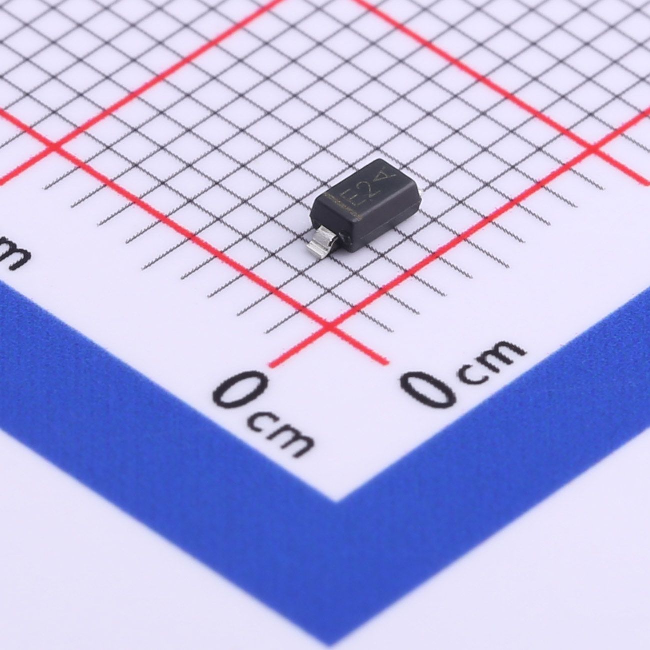
【Daily Highlight】The Voltage Regulator Diode MMSZ5232B
2026-09-30
522
IntroductionVoltage regulator diodes are a popular component in electronic circuits that help regulate voltage levels and protect sensitive electronic components from over-voltage. One such diode is the MMSZ5232B, which has a zener voltage of 5.6V and a precision of ±5%. In this article, we'll take a closer look at the MMSZ5232B and its specifications.
Slkor Voltage Regulator Diode MMSZ5232B product photo
Slkor Zener diode MMSZ5232B specification
Voltage Zener (VZTyp) and Precision
The MMSZ5232B voltage regulator diode has a Zener voltage of 5.6V. The Zener voltage specification indicates the voltage at which the diode will begin conducting current. For example, if the voltage across the diode exceeds 5.6V, the diode will start to conduct and regulate the voltage. This makes the MMSZ5232B an ideal choice for applications where a stable voltage is required.
The precision of the MMSZ5232B is ±5%.This means that the actual Zener voltage can vary by up to 5% from the nominal value of 5.6V. This tolerance is important to consider when designing circuits that require precise voltage regulation.
Power Dissipation (PD)
The MMSZ5232B has a power dissipation rating (PD) of 500mW. The PD specification indicates the amount of power the diode can safely dissipate as heat without being damaged. In other words, the PD specification tells us how much power the diode can handle before it overheats and fails. It's important to ensure that the operating conditions of the diode do not exceed its PD rating to prevent damage.
Reverse Current (Ir)
The MMSZ5232B has a reverse current rating (Ir) of 5nA at 3V. The Ir specification indicates the amount of current that will flow through the diode in the reverse direction when a voltage is applied in that direction. In other words, it tells us how much current will leak through the diode when it's supposed to be blocking the flow of current. The lower the Ir rating, the better the diode is at preventing reverse current from flowing.
Parameters of Slkor Zener diode MMSZ5232B
Conclusion
In summary, the MMSZ5232B is a voltage regulator diode with a Zener voltage of 5.6V and a precision of ±5%. It has a power dissipation rating of 500mW and a reverse current rating of 5nA at 3V. These specifications make the MMSZ5232B an ideal choice for applications where precise voltage regulation is required, and where protection against over-voltage and reverse current is necessary.
What is the technology and product roadmap of Slkor?
Slkor's technology roadmap primarily focuses on power devices, TVS diodes, and other similar products. The company plans to gradually expand its product line to include ADC series products, MCUs, and other active devices. By combining active and passive components under the "SLKOR" brand, Slkor offers a range of products for customers to choose from, enhancing interaction and stickiness with end customers. This strategy strengthens bargaining power and increases competitive advantage, thus laying a solid foundation for increasing sales revenue and gross profit.
About Slkor:
Slkor has research and development offices in Busan, South Korea, Beijing, China, and Suzhou, China. Most of the wafer manufacturing and packaging and testing are carried out within China. The company employs and collaborates with individuals and organizations worldwide, with a laboratory for product performance and reliability testing and a central warehouse located at its headquarters in Shenzhen. Slkor has filed for over a hundred invention patents, offers more than 2,000 product models, and serves over ten thousand customers globally. Its products are exported to countries and regions including Europe, the Americas, Southeast Asia, and the Middle East, making it one of the rapidly growing semiconductor companies in recent years. With well-established management systems and streamlined workflows, Slkor has rapidly enhanced the brand awareness and reputation of its "SLKOR" brand through its outstanding quality and standardized services. Its product range includes three major series: diodes, transistors, and power devices, with recent introductions of new products such as Hall elements and analog devices, expanding its presence in sensors, Risc-v microcontrollers, and other product categories.
MMSZ5232BTo Product Page
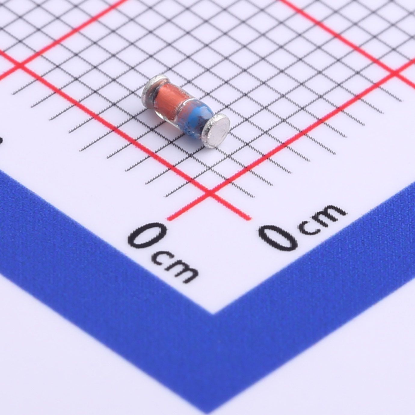
【Daily Highlight】The Voltage Regulator Diode ZMM24
2026-09-30
528
ZMM24 is a popular zener diode widely used in electronic circuits due to its excellent characteristics. It is a 24V zener diode, and the VZTyp-24V parameter denotes its typical voltage rating. The diode has a maximum power dissipation (PD) of 500mW, which means it can handle up to 500 milliwatts of power without getting damaged. Additionally, the diode has an extremely low reverse current (Ir) of 100nA at 18V.
Slkor Voltage Regulator Diode ZMM24 product photo
Zener diodes are semiconductor devices that allow current flow in one direction and block it in the opposite direction. They are designed to operate in the reverse breakdown region, where a small change in voltage causes a large change in current. Zener diodes are unique in that they have a specific breakdown voltage, beyond which they start conducting heavily. This feature makes them ideal for use in voltage regulation circuits.
Slkor Zener diode ZMM24 specification
The ZMM24 zener diode has a breakdown voltage of 24V, which means it maintains a constant voltage of 24V across its terminals when the voltage across it exceeds this value. This characteristic makes it ideal for use in voltage regulation circuits that require a stable output voltage. The zener diode can regulate voltage by shunting excess current when the voltage across the circuit exceeds the zener voltage.
The ZMM24 zener diode has a maximum power dissipation of 500mW, which means it can handle up to 500 milliwatts of power without getting damaged. The power dissipation rating is an important parameter to consider when designing circuits that use zener diodes. Exceeding the maximum power dissipation rating can cause the diode to overheat and get damaged.
Another important parameter of the ZMM24 zener diode is its extremely low reverse current of 100nA at 18V. Reverse current is the current that flows through the diode in the reverse direction, which can cause the circuit to malfunction. The low reverse current of the ZMM24 zener diode makes it an ideal choice for use in low-power circuits that require high precision.
Parameters of Slkor Zener diode ZMM24
The ZMM24 zener diode has various applications in electronic circuits. Here are some common applications:
Voltage Regulation: One of the primary uses of zener diodes is in voltage regulation circuits. The ZMM24, with its 24V breakdown voltage, is well-suited for regulating voltages in electronic devices and power supplies. It can be used to maintain a stable output voltage by shunting excess current when the voltage exceeds the zener voltage.
Overvoltage Protection: Zener diodes are commonly employed as voltage clamping devices to protect sensitive components from overvoltage conditions. The ZMM24 can be used in such applications to limit voltage spikes and protect circuits from damage caused by excessive voltage levels.
Signal Conditioning: Zener diodes can be used to condition signals in various electronic circuits. They can be utilized as voltage references or voltage limiters to ensure that signals stay within a specific range. The ZMM24 can play a vital role in signal conditioning applications, especially those requiring a 24V reference or limiting voltage swings.
Voltage Biasing: Zener diodes can be used as voltage biasing elements in amplifier circuits and other applications where a stable voltage reference is required. The ZMM24, with its precise breakdown voltage and low reverse current, can provide a reliable biasing voltage to ensure proper circuit operation.
Oscillator Circuits: Zener diodes can be employed in oscillator circuits to stabilize the oscillation frequency. By providing a stable reference voltage, the ZMM24 can help maintain consistent oscillation and improve the accuracy of oscillator circuits.
Temperature Compensation: Zener diodes exhibit a temperature coefficient that can be utilized for temperature compensation in electronic circuits. By selecting appropriate zener diodes, including the ZMM24, it is possible to compensate for variations in temperature and maintain circuit performance across different temperature ranges.
It's important to note that while these are common applications, the ZMM24 zener diode can be used in various other circuit configurations depending on specific requirements. Its characteristics make it suitable for a wide range of voltage regulation and precision circuit applications.
Slkor using AI technology
In the era of informatization and intelligence, using intelligent tools is an inevitable choice for business development. Both SLKOR Semiconductor (www.slkoric.com) and Kinghelm (www.kinghelm.com.cn) are keeping up with the trend of the times, not only focusing on technological research and development in the semiconductor field and antenna connectors but also paying attention to digitalization and intelligent services. Recently, the SLKOR WeChat public account has embedded a large-scale AI robot, which is a major innovation in intelligent services. Through artificial intelligence interaction, the robot can provide diversified, timely, and comprehensive service experiences for company colleagues, peers, and customers. Whether it's product consultation, technical support, or market information, the SLKOR AI robot can quickly respond to user needs and help solve problems. This 24/7, all-encompassing service model is exactly what SLKOR Semiconductor needs in the digital age - an efficient and convenient service approach. Our ultimate goal in using AI robots is to provide end-to-end services such as customer information consultation, material quoting, transaction matching, and goods delivery arrangements.
About Slkor:
Slkor has research and development offices in Busan, South Korea, Beijing, China, and Suzhou, China. Most of the wafer manufacturing and packaging and testing are carried out within China. The company employs and collaborates with individuals and organizations worldwide, with a laboratory for product performance and reliability testing and a central warehouse located at its headquarters in Shenzhen. Slkor has filed for over a hundred invention patents, offers more than 2,000 product models, and serves over ten thousand customers globally. Its products are exported to countries and regions including Europe, the Americas, Southeast Asia, and the Middle East, making it one of the rapidly growing semiconductor companies in recent years. With well-established management systems and streamlined workflows, Slkor has rapidly enhanced the brand awareness and reputation of its "SLKOR" brand through its outstanding quality and standardized services. Its product range includes three major series: diodes, transistors, and power devices, with recent introductions of new products such as Hall elements and analog devices, expanding its presence in sensors, Risc-v microcontrollers, and other product categories.
ZMM24To Product Page
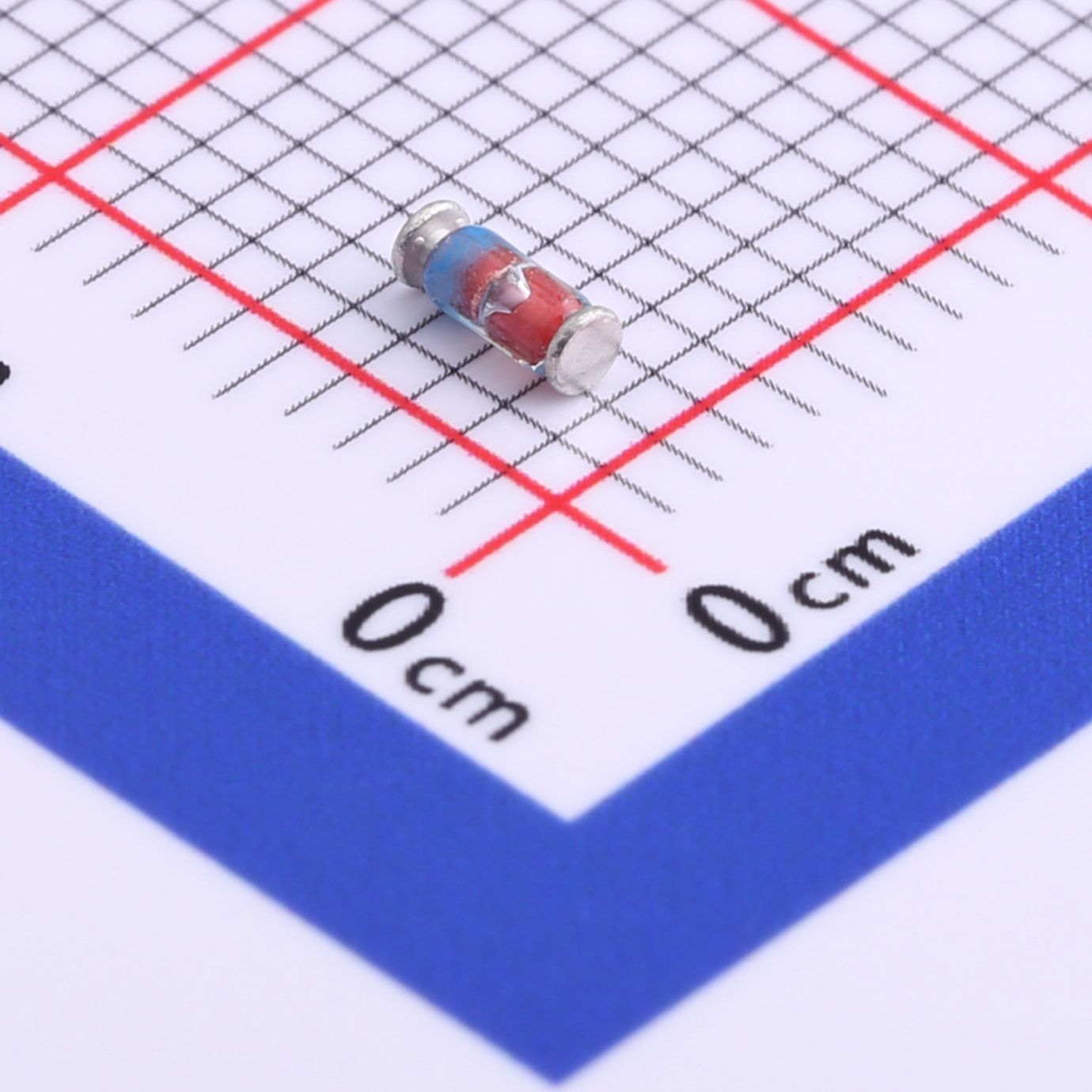
【Daily Highlight】The Voltage Regulator Diode ZMM2V7
2026-09-30
522
The ZMM2V7 is a popular zener diode widely used in electronic circuits for voltage regulation and protection purposes. The VZTyp-2.7V parameter denotes its typical voltage rating, which means it maintains a constant voltage of 2.7V across its terminals when the voltage across it exceeds this value. This characteristic makes it ideal for use in circuits that require a stable output voltage.
Slkor Voltage Regulator Diode ZMM2V7 product photo
The ZMM2V7 zener diode has a maximum power dissipation (PD) of 500mW, which means it can handle up to 500 milliwatts of power without getting damaged. This rating is an important parameter to consider when designing circuits that use zener diodes. Exceeding the maximum power dissipation rating can cause the diode to overheat and get damaged.
Another important parameter of the ZMM2V7 zener diode is its extremely low reverse current (Ir) of 10μA at 1V. Reverse current is the current that flows through the diode in the reverse direction, which can cause the circuit to malfunction. The low reverse current of the ZMM2V7 zener diode makes it an ideal choice for use in low-power circuits that require high precision.
The ZMM2V7 zener diode is available in a variety of packages, including SOD-80, DO-35, and SOD-123. The SOD-80 is the smallest package, while the SOD-123 is the largest. The package size is an important consideration when designing circuits with limited board space.
Slkor Zener diode ZMM2V7 specification
Parameters of Slkor Zener diode ZMM2V7
The ZMM2V7 zener diode offers several advantages that make it a popular choice in electronic circuit design. Here are some of its key advantages:
Voltage Regulation: The primary advantage of the ZMM2V7 zener diode is its ability to provide voltage regulation. It maintains a constant voltage of 2.7V across its terminals, even when the voltage across it exceeds this value. This characteristic is crucial in applications where a stable output voltage is required, such as in power supplies and electronic devices.
Precise Voltage Reference: The ZMM2V7 zener diode provides a precise voltage reference of 2.7V, which is beneficial in circuits that require accurate and stable voltage levels. It can be used as a reference for setting operational voltages or as a voltage limiter to ensure signals stay within a specific range.
Overvoltage Protection: Zener diodes, including the ZMM2V7, act as effective voltage clamping devices, protecting sensitive components from overvoltage conditions. When the voltage exceeds the zener voltage (2.7V in this case), the diode starts conducting heavily, diverting excess current and limiting the voltage across the circuit. This protects the circuitry and prevents damage to components.
Low Reverse Current: The ZMM2V7 zener diode has an extremely low reverse current of 10μA at 1V. This low reverse current is desirable in circuits that require precision and low-power operation. It ensures that minimal current flows through the diode in the reverse direction, reducing power consumption and improving overall circuit efficiency.
Temperature Stability: Zener diodes, including the ZMM2V7, exhibit good temperature stability characteristics. They have a low temperature coefficient, which means their breakdown voltage remains relatively constant over a wide temperature range. This stability is crucial in applications where the circuit's performance needs to be maintained across varying temperatures.
Wide Availability and Package Options: The ZMM2V7 zener diode is widely available from various manufacturers. It is offered in different package options, such as SOD-80, DO-35, and SOD-123, providing flexibility in circuit design and accommodating different space requirements.
Cost-Effective: Zener diodes, including the ZMM2V7, are generally cost-effective components, making them accessible and affordable for a wide range of applications. Their affordability, combined with their reliability and versatility, makes them a preferred choice in many electronic circuit designs.
Overall, the ZMM2V7 zener diode offers advantages such as voltage regulation, precise voltage reference, overvoltage protection, low reverse current, temperature stability, availability in different packages, and cost-effectiveness. These advantages make the ZMM2V7 suitable for numerous electronic circuit applications where stable voltage regulation and protection are essential.
Slkor using AI technology
In the era of informatization and intelligence, using intelligent tools is an inevitable choice for business development. Both SLKOR Semiconductor (www.slkoric.com) and Kinghelm (www.kinghelm.com.cn) are keeping up with the trend of the times, not only focusing on technological research and development in the semiconductor field and antenna connectors but also paying attention to digitalization and intelligent services. Recently, the SLKOR WeChat public account has embedded a large-scale AI robot, which is a major innovation in intelligent services. Through artificial intelligence interaction, the robot can provide diversified, timely, and comprehensive service experiences for company colleagues, peers, and customers. Whether it's product consultation, technical support, or market information, the SLKOR AI robot can quickly respond to user needs and help solve problems. This 24/7, all-encompassing service model is exactly what SLKOR Semiconductor needs in the digital age - an efficient and convenient service approach. Our ultimate goal in using AI robots is to provide end-to-end services such as customer information consultation, material quoting, transaction matching, and goods delivery arrangements.
About Slkor:
Slkor has research and development offices in Busan, South Korea, Beijing, China, and Suzhou, China. Most of the wafer manufacturing and packaging and testing are carried out within China. The company employs and collaborates with individuals and organizations worldwide, with a laboratory for product performance and reliability testing and a central warehouse located at its headquarters in Shenzhen. Slkor has filed for over a hundred invention patents, offers more than 2,000 product models, and serves over ten thousand customers globally. Its products are exported to countries and regions including Europe, the Americas, Southeast Asia, and the Middle East, making it one of the rapidly growing semiconductor companies in recent years. With well-established management systems and streamlined workflows, Slkor has rapidly enhanced the brand awareness and reputation of its "SLKOR" brand through its outstanding quality and standardized services. Its product range includes three major series: diodes, transistors, and power devices, with recent introductions of new products such as Hall elements and analog devices, expanding its presence in sensors, Risc-v microcontrollers, and other product categories.
ZMM2V7To Product Page
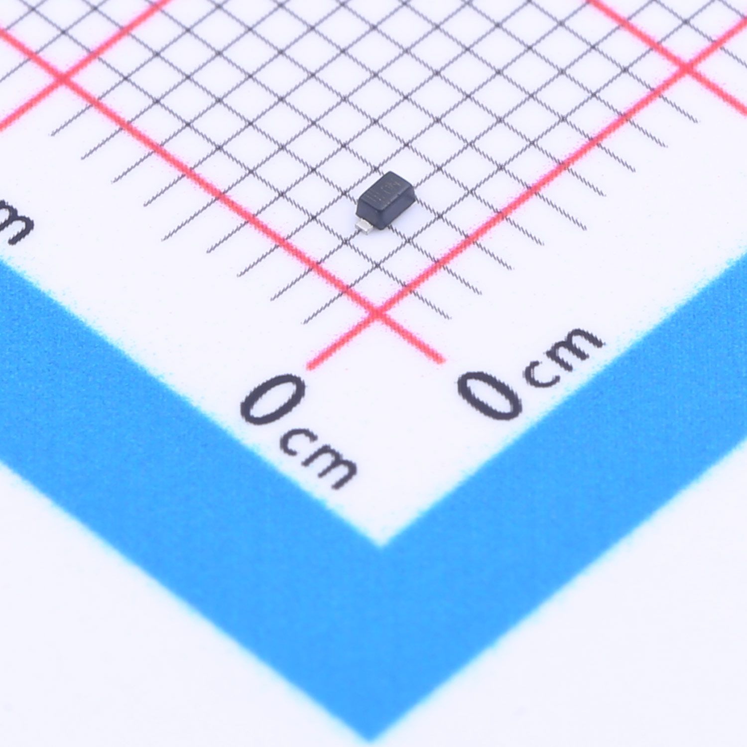
【Daily Highlight】The Voltage Regulator Diode MM5Z12V
2026-09-30
519
Introduction:
Zener diodes play a crucial role in electronic circuits, providing voltage regulation, overvoltage protection, and precise voltage references. The MM5Z12V zener diode is a component with specific characteristics that make it suitable for various applications. This article delves into an in-depth analysis of the MM5Z12V zener diode, exploring its parameters, performance, and potential applications.
Slkor Voltage Regulator Diode MM5Z12V product photo
MM5Z12V Zener Diode Overview:
The MM5Z12V zener diode is a semiconductor device designed to maintain a stable voltage across its terminals when operated in the breakdown region. Its key parameters define its behavior and suitability for different circuit requirements.
Slkor Zener diode MM5Z12V specification
Key Parameters:
VZTyp (Typical Zener Voltage): The typical zener voltage, VZTyp, for the MM5Z12V is specified as 12V. This parameter represents the expected voltage at which the zener diode begins conducting and provides a relatively constant voltage output.
VZ Range: The allowable zener voltage range for the MM5Z12V is specified as 11.4V to 12.7V. This range accounts for manufacturing tolerances and operating conditions, ensuring that the zener diode's actual voltage characteristics fall within this specified range.
Maximum Power Dissipation (PD): The maximum power dissipation specification of 200mW denotes the highest amount of power that the zener diode can handle without sustaining damage. This parameter is critical for determining the diode's thermal stability and safe operating limits in practical circuits.
Reverse Current (Ir) at 9V: The reverse current specification of 100nA at 9V indicates the small amount of current that flows through the diode in the reverse direction when a reverse bias voltage of 9V is applied. This low reverse current is integral for applications requiring minimal leakage current and high precision.
Dynamic Impedance (Zzt): The dynamic impedance of 25Ω represents the small-signal impedance of the zener diode when it is conducting. This parameter is essential for understanding the diode's behavior under varying AC or small-signal conditions, providing insights into its performance in dynamic circuits.
Parameters of Slkor Zener diode MM5Z12V
Performance and Applications:
The MM5Z12V zener diode's specifications position it as a valuable component for various applications. Its stable zener voltage, wide operating range, low reverse current, and moderate dynamic impedance contribute to its versatility and utility in electronic circuits. Some potential applications of the MM5Z12V zener diode include:
Voltage Regulation: The MM5Z12V can be utilized to provide stable reference voltages in power supplies, voltage regulators, and precision analog circuits, ensuring consistent and reliable voltage levels.
Overvoltage Protection: Due to its specified voltage range and low dynamic impedance, the MM5Z12V offers effective overvoltage protection in electronic circuits, safeguarding sensitive components from voltage spikes and transients.
Precision Circuits: Its low reverse current and precise zener voltage make the MM5Z12V suitable for precision instruments, sensor interfaces, and measurement circuits where accuracy and stability are paramount.
Conclusion:
The MM5Z12V zener diode stands out as a versatile and reliable component with specific characteristics that cater to the needs of modern electronic circuits. Its defined parameters, including typical zener voltage, voltage range, power dissipation, reverse current, and dynamic impedance, enable engineers to design circuits with precise voltage regulation, overvoltage protection, and high precision. Understanding the capabilities and limitations of the MM5Z12V zener diode empowers designers to make informed choices when integrating this component into their electronic systems, ultimately contributing to the creation of robust and efficient circuitry.
Slkor using AI technology
In the era of informatization and intelligence, using intelligent tools is an inevitable choice for business development. Both SLKOR Semiconductor (www.slkoric.com) and Kinghelm (www.kinghelm.com.cn) are keeping up with the trend of the times, not only focusing on technological research and development in the semiconductor field and antenna connectors but also paying attention to digitalization and intelligent services. Recently, the SLKOR WeChat public account has embedded a large-scale AI robot, which is a major innovation in intelligent services. Through artificial intelligence interaction, the robot can provide diversified, timely, and comprehensive service experiences for company colleagues, peers, and customers. Whether it's product consultation, technical support, or market information, the SLKOR AI robot can quickly respond to user needs and help solve problems. This 24/7, all-encompassing service model is exactly what SLKOR Semiconductor needs in the digital age - an efficient and convenient service approach. Our ultimate goal in using AI robots is to provide end-to-end services such as customer information consultation, material quoting, transaction matching, and goods delivery arrangements.
About Slkor:Slkor has research and development offices in Busan, South Korea, Beijing, China, and Suzhou, China. Most of the wafer manufacturing and packaging and testing are carried out within China. The company employs and collaborates with individuals and organizations worldwide, with a laboratory for product performance and reliability testing and a central warehouse located at its headquarters in Shenzhen. Slkor has filed for over a hundred invention patents, offers more than 2,000 product models, and serves over ten thousand customers globally. Its products are exported to countries and regions including Europe, the Americas, Southeast Asia, and the Middle East, making it one of the rapidly growing semiconductor companies in recent years. With well-established management systems and streamlined workflows, Slkor has rapidly enhanced the brand awareness and reputation of its "SLKOR" brand through its outstanding quality and standardized services. Its product range includes three major series: diodes, transistors, and power devices, with recent introductions of new products such as Hall elements and analog devices, expanding its presence in sensors, Risc-v microcontrollers, and other product categories.
MM5Z12VTo Product Page
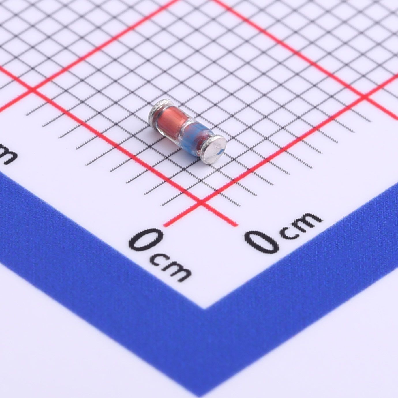
【Daily Highlight】The Voltage Regulator Diode ZMM6V2
2026-09-30
501
Introduction:
Zener diodes are fundamental components in electronic circuits, providing voltage regulation, overvoltage protection, and reference voltage generation. The ZMM6V2 zener diode is a vital semiconductor device with specific parameters that define its behavior and suitability for diverse applications. This article offers an in-depth analysis of the ZMM6V2 zener diode, delving into its key parameters, performance characteristics, and potential applications.
Slkor Voltage Regulator Diode ZMM6V2 product photo
Overview of ZMM6V2 Zener Diode:
The ZMM6V2 zener diode is designed to maintain a stable voltage across its terminals when operated in the breakdown region. Its distinct parameters play a critical role in determining its functionality and application-specific considerations.
Slkor Zener diode ZMM6V2 specification
Key Parameters:
VZTyp (Typical Zener Voltage): The typical zener voltage, VZTyp, for the ZMM6V2 is specified as 6.2V. This parameter signifies the expected voltage at which the zener diode initiates conduction and provides a relatively constant voltage output.
Maximum Power Dissipation (PD): The ZMM6V2 zener diode exhibits a maximum power dissipation capability of 500mW. This specification indicates the highest amount of power that the diode can dissipate without sustaining damage, offering insights into its thermal handling capacity and safe operational limits in practical circuits.
Reverse Current (Ir) at 2V: At a reverse bias voltage of 2V, the ZMM6V2 zener diode demonstrates a reverse current of 100nA. This parameter represents the minimal amount of current that flows through the diode in the reverse direction, signifying low leakage current and suitability for high-precision applications.
Parameters of Slkor Zener diode ZMM6V2
Performance and Applications:
The ZMM6V2 zener diode's specifications position it as a valuable component for various electronic applications. Its stable zener voltage, substantial power dissipation capability, and low reverse current make it well-suited for diverse circuit requirements. Some potential applications of the ZMM6V2 zener diode include:
Voltage Regulation: The ZMM6V2 can be employed in voltage regulation circuits, such as voltage references, voltage clamps, and power supplies, ensuring stable and consistent voltage levels in electronic systems.
Overvoltage Protection: Due to its defined zener voltage and robust power dissipation, the ZMM6V2 offers effective protection against overvoltage events, safeguarding sensitive components from voltage surges and transients.
Precision Instrumentation: Its low reverse current and stable zener voltage make the ZMM6V2 suitable for precision measuring instruments, sensor interfaces, and data acquisition systems, where accuracy and reliability are paramount.
Conclusion:
The ZMM6V2 zener diode emerges as a versatile and dependable component with specific characteristics that cater to the demands of modern electronic circuits. Its typical zener voltage, power dissipation capability, and reverse current specifications enable engineers to design circuits with precise voltage regulation, overvoltage protection, and high precision. Understanding the capabilities and limitations of the ZMM6V2 zener diode empowers designers to make informed decisions when integrating this component into their electronic systems, contributing to the creation of resilient and efficient circuitry.
Slkor using AI technology
In the era of informatization and intelligence, using intelligent tools is an inevitable choice for business development. Both SLKOR Semiconductor (www.slkoric.com) and Kinghelm (www.kinghelm.com.cn) are keeping up with the trend of the times, not only focusing on technological research and development in the semiconductor field and antenna connectors but also paying attention to digitalization and intelligent services. Recently, the SLKOR WeChat public account has embedded a large-scale AI robot, which is a major innovation in intelligent services. Through artificial intelligence interaction, the robot can provide diversified, timely, and comprehensive service experiences for company colleagues, peers, and customers. Whether it's product consultation, technical support, or market information, the SLKOR AI robot can quickly respond to user needs and help solve problems. This 24/7, all-encompassing service model is exactly what SLKOR Semiconductor needs in the digital age - an efficient and convenient service approach. Our ultimate goal in using AI robots is to provide end-to-end services such as customer information consultation, material quoting, transaction matching, and goods delivery arrangements.
About Slkor:Slkor has research and development offices in Busan, South Korea, Beijing, China, and Suzhou, China. Most of the wafer manufacturing and packaging and testing are carried out within China. The company employs and collaborates with individuals and organizations worldwide, with a laboratory for product performance and reliability testing and a central warehouse located at its headquarters in Shenzhen. Slkor has filed for over a hundred invention patents, offers more than 2,000 product models, and serves over ten thousand customers globally. Its products are exported to countries and regions including Europe, the Americas, Southeast Asia, and the Middle East, making it one of the rapidly growing semiconductor companies in recent years. With well-established management systems and streamlined workflows, Slkor has rapidly enhanced the brand awareness and reputation of its "SLKOR" brand through its outstanding quality and standardized services. Its product range includes three major series: diodes, transistors, and power devices, with recent introductions of new products such as Hall elements and analog devices, expanding its presence in sensors, Risc-v microcontrollers, and other product categories.
ZMM6V2To Product Page
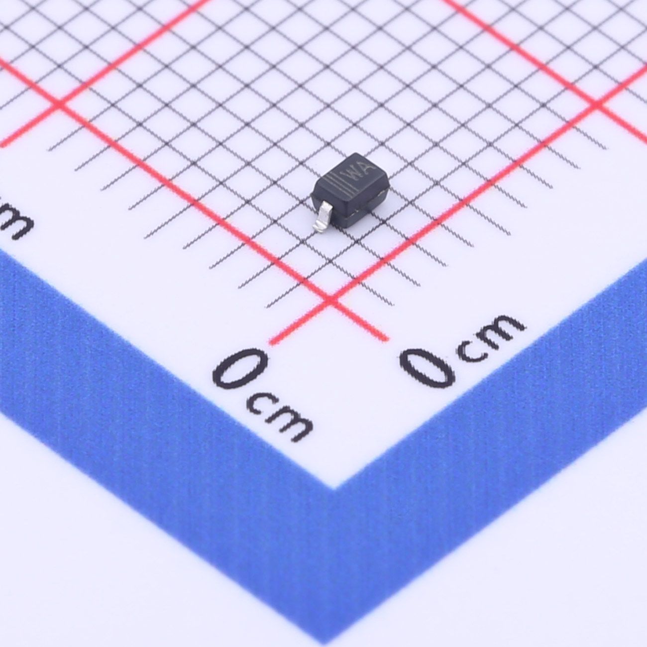
【Daily Highlight】The Voltage Regulator Diode BZT52C6V2S
2026-09-30
504
Introduction:
Zener diodes are essential components in electronic circuits, offering precise voltage regulation, overvoltage protection, and stable reference voltages. The BZT52C6V2S zener diode stands as a crucial semiconductor device with specific parameters that define its behavior and suitability for diverse applications. This article provides a comprehensive analysis of the BZT52C6V2S zener diode, exploring its key parameters, performance characteristics, and potential applications.
Slkor Voltage Regulator Diode BZT52C6V2S product photo
Overview of BZT52C6V2S Zener Diode:
The BZT52C6V2S zener diode is engineered to maintain a stable voltage across its terminals when operated in the breakdown region. Its distinct parameters play a pivotal role in determining its functionality and relevance for various circuit requirements.
Slkor Zener diode BZT52C6V2S specification
Key Parameters:
VZTyp (Typical Zener Voltage): The typical zener voltage, VZTyp, for the BZT52C6V2S is specified as 6.2V. This parameter indicates the expected voltage at which the zener diode commences conduction, providing a relatively constant voltage output.
VZ Range: The allowable zener voltage range for the BZT52C6V2S spans from 5.8V to 6.6V. This range accommodates manufacturing tolerances and operational conditions, ensuring that the zener diode's actual voltage characteristics fall within this specified range.
Maximum Power Dissipation (PD): The BZT52C6V2S zener diode boasts a maximum power dissipation capability of 200mW. This specification represents the highest amount of power that the diode can dissipate without sustaining damage, offering insights into its thermal handling capacity and safe operational limits in practical circuits.
Reverse Current (Ir) at 4V: At a reverse bias voltage of 4V, the BZT52C6V2S zener diode demonstrates a reverse current of 3μA. This parameter reflects the minimal amount of current that flows through the diode in the reverse direction, indicating low leakage current and suitability for high-precision applications.
Dynamic Impedance (Zzt): The dynamic impedance of 10Ω represents the small-signal impedance of the zener diode when it is conducting. This parameter is crucial for understanding the diode's behavior under varying AC or small-signal conditions, providing insights into its performance in dynamic circuits.
Parameters of Slkor Zener diode BZT52C6V2S
Performance and Applications:
The BZT52C6V2S zener diode's specifications position it as a valuable component for various electronic applications. Its stable zener voltage, defined voltage range, moderate power dissipation capability, low reverse current, and modest dynamic impedance make it well-suited for diverse circuit requirements. Some potential applications of the BZT52C6V2S zener diode include:
Voltage Regulation: The BZT52C6V2S can be utilized in voltage regulation circuits, such as voltage references, voltage limiters, and power supplies, ensuring stable and consistent voltage levels in electronic systems.
Overvoltage Protection: Due to its specified voltage range and robust power dissipation, the BZT52C6V2S offers effective protection against overvoltage events, safeguarding sensitive components from voltage spikes and transients.
Precision Instrumentation: Its low reverse current and stable zener voltage make the BZT52C6V2S suitable for precision measuring instruments, sensor interfaces, and data acquisition systems, where accuracy and reliability are paramount.
Conclusion:
The BZT52C6V2S zener diode emerges as a versatile and dependable component with specific characteristics that cater to the demands of modern electronic circuits. Its typical zener voltage, specified voltage range, power dissipation capability, reverse current, and dynamic impedance enable engineers to design circuits with precise voltage regulation, overvoltage protection, and high precision. Understanding the capabilities and limitations of the BZT52C6V2S zener diode empowers designers to make informed decisions when integrating this component into their electronic systems, contributing to the creation of resilient and efficient circuitry.
Slkor using AI technology
In the era of informatization and intelligence, using intelligent tools is an inevitable choice for business development. Both SLKOR Semiconductor (www.slkoric.com) and Kinghelm (www.kinghelm.com.cn) are keeping up with the trend of the times, not only focusing on technological research and development in the semiconductor field and antenna connectors but also paying attention to digitalization and intelligent services. Recently, the SLKOR WeChat public account has embedded a large-scale AI robot, which is a major innovation in intelligent services. Through artificial intelligence interaction, the robot can provide diversified, timely, and comprehensive service experiences for company colleagues, peers, and customers. Whether it's product consultation, technical support, or market information, the SLKOR AI robot can quickly respond to user needs and help solve problems. This 24/7, all-encompassing service model is exactly what SLKOR Semiconductor needs in the digital age - an efficient and convenient service approach. Our ultimate goal in using AI robots is to provide end-to-end services such as customer information consultation, material quoting, transaction matching, and goods delivery arrangements.
About Slkor:Slkor has research and development offices in Busan, South Korea, Beijing, China, and Suzhou, China. Most of the wafer manufacturing and packaging and testing are carried out within China. The company employs and collaborates with individuals and organizations worldwide, with a laboratory for product performance and reliability testing and a central warehouse located at its headquarters in Shenzhen. Slkor has filed for over a hundred invention patents, offers more than 2,000 product models, and serves over ten thousand customers globally. Its products are exported to countries and regions including Europe, the Americas, Southeast Asia, and the Middle East, making it one of the rapidly growing semiconductor companies in recent years. With well-established management systems and streamlined workflows, Slkor has rapidly enhanced the brand awareness and reputation of its "SLKOR" brand through its outstanding quality and standardized services. Its product range includes three major series: diodes, transistors, and power devices, with recent introductions of new products such as Hall elements and analog devices, expanding its presence in sensors, Risc-v microcontrollers, and other product categories.
BZT52C6V2STo Product Page
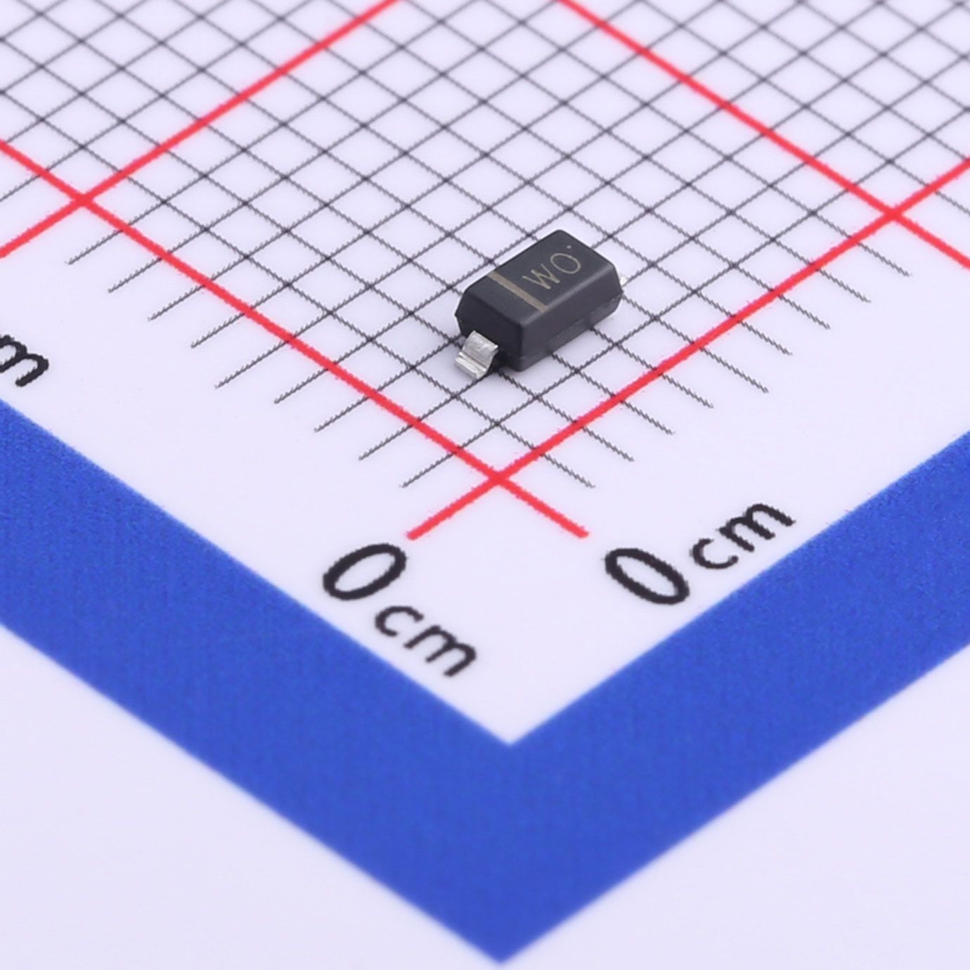
【Daily Highlight】The Voltage Regulator Diode BZT52C24
2026-09-30
532
Introduction:
Zener diodes play a critical role in electronic circuits, providing precise voltage regulation, overvoltage protection, and stable reference voltages. The BZT52C24 zener diode is a fundamental semiconductor device with specific parameters that define its behavior and suitability for various applications. This article offers a comprehensive analysis of the BZT52C24 zener diode, delving into its key parameters, performance characteristics, and potential applications.
Slkor Voltage Regulator Diode BZT52C24 product photo
Overview of BZT52C24 Zener Diode:
The BZT52C24 zener diode is designed to maintain a stable voltage across its terminals when operated in the breakdown region. Its distinctive parameters play a pivotal role in defining its functionality and relevance for diverse circuit requirements.
Slkor Voltage Regulator Diode BZT52C24 specification
Key Parameters:
VZTyp (Typical Zener Voltage): The typical zener voltage, VZTyp, for the BZT52C24 is specified as 24V. This parameter indicates the expected voltage at which the zener diode begins conducting, providing a relatively constant voltage output.
Maximum Power Dissipation (PD): The BZT52C24 zener diode exhibits a maximum power dissipation capability of 500mW. This specification represents the highest amount of power that the diode can dissipate without sustaining damage, offering insights into its thermal handling capacity and safe operational limits in practical circuits.
Reverse Current (Ir) at 16.8V: At a reverse bias voltage of 16.8V, the BZT52C24 zener diode demonstrates a reverse current of 100nA. This parameter reflects the minimal amount of current that flows through the diode in the reverse direction, indicating low leakage current and suitability for high-precision applications.
Parameters of Slkor Voltage Regulator Diode BZT52C24
Performance and Applications:
The BZT52C24 zener diode's specifications position it as a valuable component for various electronic applications due to its stable zener voltage, robust power dissipation capability, and low reverse current. Some potential applications of the BZT52C24 zener diode include:
Voltage Regulation: The BZT52C24 can be used in voltage regulation circuits, voltage references, and power supplies to ensure stable and consistent voltage levels in electronic systems, especially in systems requiring a 24V reference voltage.
Overvoltage Protection: With its high power dissipation capability, the BZT52C24 offers effective protection against overvoltage events, safeguarding sensitive components from voltage spikes and transients in systems operating with a 24V power supply.
Precision Instrumentation: The low reverse current and stable zener voltage make the BZT52C24 suitable for precision measuring instruments, sensor interfaces, and data acquisition systems that demand accuracy and reliability at a 24V bias.
Conclusion:
The BZT52C24 zener diode stands as a fundamental component with specific characteristics that cater to the demands of modern electronic circuits. Its typical zener voltage, power dissipation capability, and reverse current make it well-suited for diverse circuit requirements, including voltage regulation, overvoltage protection, and high precision at a 24V reference. Understanding the capabilities and limitations of the BZT52C24 zener diode empowers engineers to make informed decisions when integrating this component into their electronic systems, leading to the creation of resilient and efficient circuitry.
Slkor using AI technology
In the era of informatization and intelligence, using intelligent tools is an inevitable choice for business development. Both SLKOR Semiconductor (www.slkoric.com) and Kinghelm (www.kinghelm.com.cn) are keeping up with the trend of the times, not only focusing on technological research and development in the semiconductor field and antenna connectors but also paying attention to digitalization and intelligent services. Recently, the SLKOR WeChat public account has embedded a large-scale AI robot, which is a major innovation in intelligent services. Through artificial intelligence interaction, the robot can provide diversified, timely, and comprehensive service experiences for company colleagues, peers, and customers. Whether it's product consultation, technical support, or market information, the SLKOR AI robot can quickly respond to user needs and help solve problems. This 24/7, all-encompassing service model is exactly what SLKOR Semiconductor needs in the digital age - an efficient and convenient service approach. Our ultimate goal in using AI robots is to provide end-to-end services such as customer information consultation, material quoting, transaction matching, and goods delivery arrangements.
About Slkor:Slkor has research and development offices in Busan, South Korea, Beijing, China, and Suzhou, China. Most of the wafer manufacturing and packaging and testing are carried out within China. The company employs and collaborates with individuals and organizations worldwide, with a laboratory for product performance and reliability testing and a central warehouse located at its headquarters in Shenzhen. Slkor has filed for over a hundred invention patents, offers more than 2,000 product models, and serves over ten thousand customers globally. Its products are exported to countries and regions including Europe, the Americas, Southeast Asia, and the Middle East, making it one of the rapidly growing semiconductor companies in recent years. With well-established management systems and streamlined workflows, Slkor has rapidly enhanced the brand awareness and reputation of its "SLKOR" brand through its outstanding quality and standardized services. Its product range includes three major series: diodes, transistors, and power devices, with recent introductions of new products such as Hall elements and analog devices, expanding its presence in sensors, Risc-v microcontrollers, and other product categories.
BZT52C6V2STo Product Page





 粤公网安备44030002007346号