





















Service Hotline
News

News
Basics of power management
2022-03-16
781
In this chapter, you will learn the basics of power management, including the types of circuit designs required for different applications. You'll also learn what a power management integrated circuit (PMIC) is and why today's versatile PMICs can replace various types of voltage regulators.
Master the basic knowledge of power supply
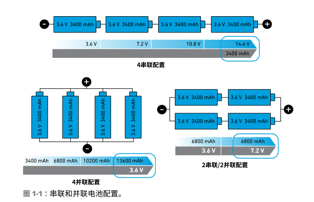
The type of DC power management subsystem required by a certain device or electronic system depends on the power source of the device or system. Possible power sources include AC, batteries, DC, and ultra-low power DC (energy harvesting). The vast majority of battery-powered electronics use lithium-ion (Li-ion) or lithium polymer (LiPo) batteries. A battery pack may contain several cells connected in series or parallel. Figure 1-1 are some examples.
Here are the voltage and current performance for each connection configuration:
-
Series cellsIt can increase the voltage of the battery pack and increase the capacity of the entire battery pack.
-
Batteries in parallelIt cannot increase the battery pack voltage, but it will improve the current control capability and current capacity of the entire battery pack.
-
Series and parallel batteriesIt can simultaneously improve voltage and current control capabilities and current capacity.
In some battery-powered applications, system components may not be able to use battery power directly. These components may require a lower or higher voltage to operate properly. During the charging and discharging process, the voltage of the battery will also change. A DC-DC converter can be used to monitor this unregulated battery input voltage and keep it stable. These converters are often called voltage regulators because they can increase, decrease, or regulate the voltage as needed (shown in Figure 1-2) and then provide the adjusted voltage to the system subcomponents.
DC-DC regulators are available in isolated and non-isolated versions, depending on whether the input ground is connected to the output ground:
-
Isolated converterUsed to isolate input and output voltages, typically using transformers or capacitive power transmission.
-
Non-isolated converterThere is a DC path connecting input ground and output ground, and the input and output ground connections are shared.
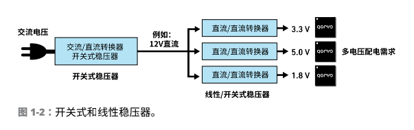
DC-DC voltage regulator classification
DC voltage regulators are divided into two categories based on the voltage conversion method used: linear regulators and switching regulators. These are two basic types of voltage regulators used in electronic devices such as cameras, cell phones, wearables, and computers. Design engineers will select the appropriate DC regulator for their system design based on input voltage, output voltage, and required current loading.
Linear regulator
Linear regulators convert the input voltage (VIN) converts to different output voltages (VOUT), using a linear component (i.e. resistive component) to regulate the output voltage VOUT. General characteristics of linear regulators:
-
Dissipate electrical energy.
-
For use with low current and low power rails.
-
Not efficient.
-
For low noise power supplies.
-
The low ripple and low noise characteristics make it suitable for sensitive analog integrated circuits such as sensors, phase-locked loops, etc.
For linear regulators, one important type is the low dropout (LDO) linear regulator. in VINand VOUTWhen the difference is very small, LDO. Can continuously output stable VOUT。
Switching voltage regulator
A switching regulator converts V via a switching elementINto a different VOUT, and use external inductors and capacitors to stabilize the output voltage VOUT. Switching regulators are generally more efficient and support higher output currents than linear regulators. But there is still ripple or switching noise after the output is regulated, even after filtering.
According to the relationship between input and output voltage, switching regulators are classified as follows:
-
Buck switching regulator: VOUT below VIN
-
Boost switching regulator: VOUT above VIN
-
Buck-Boost Switching Regulator: VOUT Variable, can be below, above, or equal to VIN
The above are the four voltage regulator topologies commonly used by design engineers? LDO and three switching regulators (buck, boost, buck-boost). In the following sections, we will introduce these four voltage regulators in detail.
LDO voltage regulator
A low dropout linear regulator is a DC linear regulator that regulates the output voltage level when the supply voltage and output voltage are very close. For LDOs, the drop voltage should be as small as possible to minimize power dissipation and maximize system efficiency (as shown in Figure 1-3).
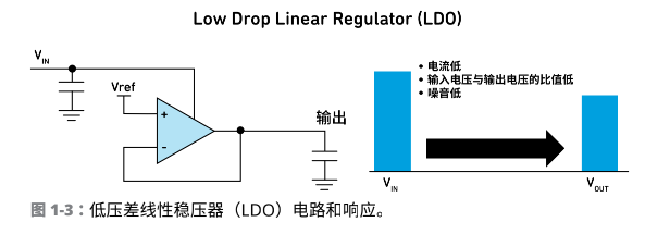
LDOs typically have a higher power supply rejection ratio (PSRR) than switching regulators, meaning the LDO can generate a low-noise output voltage. LDOs generally do not produce any ripple and are very useful in reducing input supply noise or ripple. The LDO's low standby current consumption makes it an excellent solution for portable and wireless applications.
Buck converter
here Buckmeans "to lower" or "to weaken". The buck converter is a reduced switching regulator that efficiently outputs less than VIN 的 VOUT. A buck circuit contains an inductor, a switching field-effect transistor (FET) or diode, a capacitor, and an error amplifier with a switching control circuit (shown in Figure 1-4). The buck converter changes the turn-on time of a metal-oxide-semiconductor field-effect transistor (MOSFET) and then applies power to the sensor. Buck converters have high efficiency because the MOSFET is either fully on or fully off. Between the on and off (impedance) states, a buck converter does not operate, unlike a linear regulator.
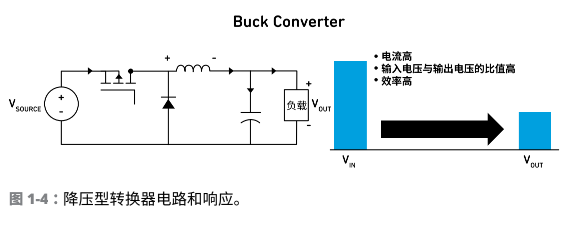
The buck converter generates switching waveforms in pulse width modulation (PWM) mode or pulse frequency modulation (PFM) mode, which are then filtered using external inductor and capacitor filter components to produce a smooth output voltage VOUT。This voltage conversion method is very efficient and can extend battery life, reduce system heat, and reduce product size.
Buck converters are used in many applications that draw power from USB and other computer peripherals. It is also used in smartphones, tablets, mobile devices, and many other electronic devices.
Boost converter
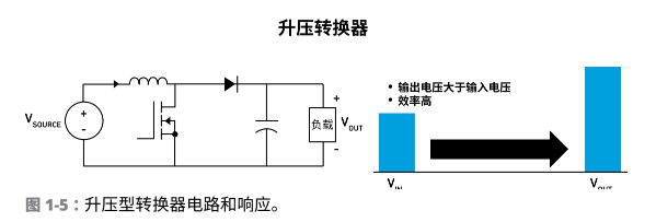
Boost Here it means "enhanced". The boost converter turns VINrises, producing VOUT. For example, when you want to convert a 3.3 volt DC input voltage to an output voltage of 5.0 volts VOUT, a boost converter would be handy. This boost operation is common in many lithium-ion or lithium-polymer battery applications.
A boost circuit contains the same components as a buck circuit (inductor, switching field-effect transistor [FET] or diode, capacitor, error amplifier with switching control circuitry) but has different connections. The boost circuit also works by controlling the turn-on time of the MOSFET to apply power to the inductor. (As shown in Figure 1-5).
Buck-Boost Converter
A buck-boost converter is a switch-mode converter that combines buck and boost in a single regulator. It can handle a wide range of input and output voltages. The control circuit adjusts the switching time of the MOSFET, reduces or increases the input voltage, and generates V as needed.OUT(As shown in Figure 1-6).
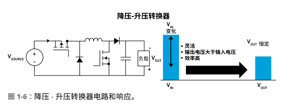
In addition to the standard buck-boost type shown in Figure 1-6, there are other types of buck-boost converters such as Sepic, Cuk, and Zeta. These converters can regulate VOUT, making it lower than, higher than or equal to VIN。
Introduction to power management integrated circuits
PMIC is an integrated circuit used for voltage conversion, voltage stabilization, and battery management. They can handle power system sequencing, power a variety of loads, and provide protection against overvoltage, undervoltage, overcurrent, thermal faults, and more.
A single PMIC can manage multiple external power supplies, mapping different system requirements to the appropriate regulator output voltage. They can also be used on a variety of processors, system controllers, and end applications by simply changing the relevant register settings or firmware without redesigning a new integrated circuit (IC).
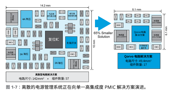
The PMIC market is growing rapidly because of several current trends. One trend is consumers' pursuit of wireless mobility, which has brought about a large demand for small, battery-operated devices, which in turn requires more highly integrated power management solutions, as shown in Figure 1-7. This figure shows how Qorvo's PMIC solution significantly reduces component count and overall solution size.
At the same time, consumers and manufacturers are increasingly demanding products that are energy-saving, environmentally friendly, and reduce carbon emissions. The global "green" trend has increased the demand for electronic products equipped with efficient power management, making power management a very important and popular feature.
All-in-one PMIC
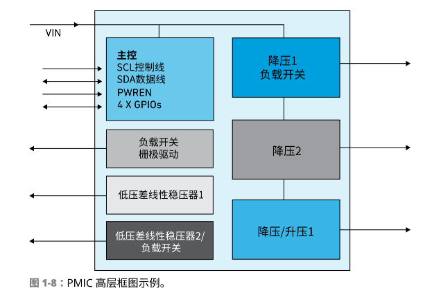
An important reason why today's PMICs are widely used is that they can satisfy many or even all voltage regulation functions in an application (as shown in Figure 1-8). These versatile PMICs can be customized through firmware for many different applications, eliminating the high cost of hardware circuit changes. These features allow them to switch smoothly between applications, thereby shortening time to market.
Disclaimer: This article is reproduced from "Xincunshe", which supports the protection of intellectual property rights. Please indicate the original source and author when reprinting. If there is any infringement, please contact us to delete it.
Company phone number: +86-0755-83044319
Fax/FAX: +86-0755-83975897
Email: 1615456225@qq.com
QQ: 3518641314 Manager Li
QQ: 332496225 Manager Qiu
Address: Room 809, Building C, Zhantao Technology Building, No. 1079 Minzhi Avenue, Longhua New District, Shenzhen
Related Recommendations
Exclusive Interview with Li Gang of Yunfan Ruida: The Precision of Millimeter-Wave Radar Products and the Warmth of Humanity
2026-07-22
2500
RF Passion, Craftsman’s Journey: Over 30 Years of Steadfast Dedication — Interview with Kinghelm Chief Engineer Mr. Qin hongxiang
2026-06-26
2672





 粤公网安备44030002007346号