
























Service Hotline
News

News
Application of closed-loop Hall current sensor in frequency converter
2022-03-16
781
summary:
The Hall effect is introduced, the working principle of the closed-loop Hall current sensor and its main features, product characteristics and selection are analyzed. The typical application of the Hall current sensor in the frequency converter and the typical current detection circuit in the frequency converter are studied and analyzed, and its typical application in the frequency converter is briefly discussed.
1. Introduction
With the continuous development of modern industrial technology, current detection is widely used in the field of industrial control. Industrial control has high requirements for the accuracy and response speed of current detection. At the same time, it hopes to achieve complete isolation from the object being detected. Hall current sensors solve these problems well. With its excellent performance and exquisite structure, Hall current sensors have become a solution for current isolation measurement in the field of industrial control, and are widely used in drives, frequency converters, motor windings, and high-frequency large current measurements.
2. Working principle
Hall current sensor is a magnetic field sensor based on the Hall effect. It has two working modes, namely open loop (direct type) and closed loop (magnetic balance type). The advantages of the direct-amplified Hall sensor are simple circuit form and relatively low cost; its disadvantages are poor accuracy and linearity, slow response time, and large temperature drift. In order to overcome its shortcomings, closed-loop (magnetic balance) Hall current sensors have emerged.
The closed-loop Hall current sensor is also called the zero-flux Hall current sensor, as shown in Figure 1. It is composed of a primary circuit, a magnetic ring, a Hall element secondary coil, an amplifier, etc. When the magnetic flux generated by the primary current IP is concentrated in the magnetic circuit through the high-quality magnetic core, the Hall element is fixed in the air gap to detect the magnetic flux, and outputs a reverse compensation current through the multi-turn coil wound on the magnetic core, which is used to offset the magnetic flux generated by the primary IP, so that the magnetic flux in the magnetic circuit always remains zero. After processing by a special circuit, the output end of the sensor can output current changes that accurately reflect the primary current.
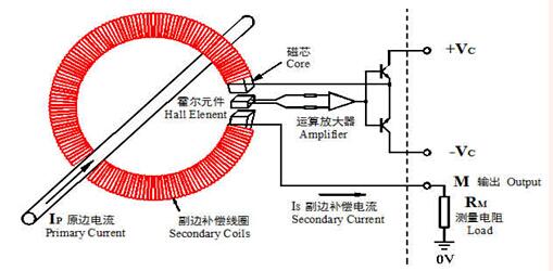
Figure 1
3. Product introduction
3.1 Product selection
Closed-loop Hall current sensors have many advantages such as short response time, high operating frequency, strong overload capability, and high isolation. Generally, the Hall current sensor is selected based on the input signal, appearance, and inner hole size. In the sensor industry, Jiangsu Ankeri Hall current sensors strictly follow the requirements stipulated in JB/T 7490-2007 "Hall Current Transformer Industry Standard". Unlike their counterparts who use pin-type wiring, they all use green pluggable terminals, making on-site wiring convenient and reliable. Common brand products are shown in Figure 2.
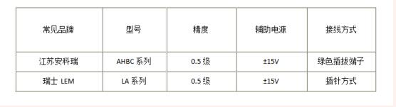
Figure 2
3.2 Product appearance
Model:AHBC-LTA
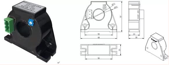
Figure 3
3.3 Technical indicators
Response time: ≤1us
Bandwidth: 100kHz
Offset current: 0.1mA
Working temperature: -25~70℃
Storage temperature: -40~80℃
Output load: Depends on different auxiliary power supplies, input signals, and output signals
Input overload capability: input 2 times the range value to resume normal operation
Withstand voltage: 3.5kV/50Hz/1min
4. Application
4.1 Sensors used in frequency conversion speed regulation circuits
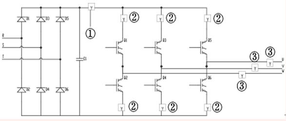
Figure 4 Frequency conversion speed regulation circuit Y is the Hall current sensor
① in Figure 4 is used to detect the DC current of the bus. When abnormal pulses are detected in the main circuit, or the effective value exceeds the standard, the trigger pulse of the inverter trigger circuit is quickly cut off to protect the inverter and rectifier modules;
② in Figure 4 is used to detect the current difference between the two bridge arms. Due to commutation failure, it is easy for the IBGT modules in the upper and lower bridge arms of one phase to be damaged due to overcurrent. At this time, the short-circuit current protection is required to cut off the gate drive circuit within 10us after the short-circuit is detected. This kind of inverter must use a fast over-current protection device. You can use Hall The current sensor detects the current in each bridge arm. If the upper and lower bridge arms are conductive at the same time due to commutation failure, the corresponding two sensors will detect the current signal at the same time. After being compared with the reference voltage and converted into a square wave, all inverter trigger pulses are blocked through gate circuit control, cutting off the short circuit path, and protecting the expensive IBGT module;
③ in Figure 4 is used to detect the waveform of the output current. It is connected to the output circuit of the inverter to detect the AC current that changes with frequency. It can better control the trigger pulse and also provide overload signals for electrical equipment.
4.2 Precautions for use
4.2.1 In order to obtain better dynamic characteristics and sensitivity, attention must be paid to the coupling of the primary coil and the secondary coil. To achieve good coupling, a single wire can be used and the wire completely fills the aperture of the Hall sensor module;
4.2.2 When a large DC current flows through the primary coil of the sensor during use, and the secondary circuit is not connected to the power supply | voltage regulator or the secondary side is open, the magnetic circuit will be magnetized, resulting in residual magnetism, which will affect the measurement accuracy (so the power supply and measuring terminal M must be connected first before use). When this happens, demagnetization must be performed first. The method is that the secondary circuit does not add power, but the same level of AC current passes through the primary coil and gradually reduces its value;
4.2.3 In most occasions, Hall sensors have strong resistance to external magnetic field interference. Generally, the magnetic field interference generated by a current twice the operating current Ip between 5-10cm away from the module can be ignored. However, when there is a stronger magnetic field interference, appropriate measures must be taken to solve it. The usual methods are:
① Adjust the module direction so that the external magnetic field has less impact on the module;
② Add a metal shield that resists magnetic fields on the module;
③ Select modules with dual Hall elements or multi-Hall elements;
④ The measurement accuracy is obtained at the rated value. When the measured current is far lower than the rated value, to obtain accuracy, multiple turns can be used on the primary side, that is: IpNp = rated ampere turns. In addition, the temperature of the primary feeder should not exceed 80°C.
5.Conclusion
Hall current sensors have many advantages. By accurately detecting and controlling large currents, they ensure the safe and reliable operation of inverter products, allowing the inverter to handle abnormal conditions in a timely manner while outputting normally, thereby improving the reliability of the inverter and improving the safety quality of the inverter. Therefore, the advantages of Hall current sensors in frequency converters are becoming more and more obvious, and they have become an indispensable part of the frequency converter industry.
【Reference】
[1] Ankerui Enterprise Microgrid Design and Application Manual 2019.11 Edition
[2] Xie Wenhe. Sensors and their applications [M]. Beijing: Higher Education Press, 2003.
[3] Yuan Junwu. Application of Hall current sensor in frequency converter
Disclaimer: This article is reproduced from "Ankerui Information Exchange", which supports the protection of intellectual property rights. Please indicate the original source and author of the reprint. If there is any infringement, please contact us to delete it.
Company phone number: +86-0755-83044319
Fax/FAX: +86-0755-83975897
Email: 1615456225@qq.com
QQ: 3518641314 Manager Li
QQ: 332496225 Manager Qiu
Address: Room 809, Building C, Zhantao Technology Building, No. 1079 Minzhi Avenue, Longhua New District, Shenzhen
Related Recommendations
Exclusive Interview with Li Gang of Yunfan Ruida: The Precision of Millimeter-Wave Radar Products and the Warmth of Humanity
2026-07-22
2503
RF Passion, Craftsman’s Journey: Over 30 Years of Steadfast Dedication — Interview with Kinghelm Chief Engineer Mr. Qin hongxiang
2026-06-26
2675





 粤公网安备44030002007346号